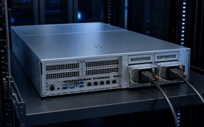
A CRPS PDB is the power distribution board assembly that accepts one or more Common Redundant Power Supply modules and connects them to the server. The PDB is not merely a cable adapter, and the CRPS modules are usually not included unless the seller explicitly describes a complete redundant power assembly. The board carries high-current output, combines or isolates module paths, routes standby power and control signals, and may carry PMBus communication to the host. For a workable purchase, the module, PDB, output harness, chassis, motherboard, and management interface must be treated as one defined subsystem.
The phrase “CRPS PDB” can describe three different deliverables
Search results, quotations, and product listings use the same short phrase for different physical scopes. A bare board may expose module receptacles and output connectors without a carrier, cable set, or supplies. A mechanical assembly may combine the board with a metal cage, module guides, mounting flange, and harness. A complete power subsystem may add matched CRPS modules and the cables needed by a particular host.
This distinction matters because the visible enclosure can make an assembly appear ready to install even when essential items are separate. A quotation should state the included module quantity, module part number or approved family, PDB revision, carrier, output cables, signal harnesses, mounting hardware, and documentation. “PDB with CRPS module inserted” in a photograph does not by itself establish that the module ships with the board.
| Quoted item | What may be included | What remains unresolved |
|---|---|---|
| Bare CRPS PDB | Printed circuit board and mounted connectors/components | Carrier, modules, cables, mounting, host support |
| PDB assembly | Board, cage or bracket, module guides, possibly harnesses | Exact PSU compatibility and host interface |
| Redundant power assembly | PDB assembly plus specified modules and cables | Chassis fit, motherboard/BMC support, deployed limits |
The assembly boundary explains where each function lives
A CRPS module converts its input to the required server-side output and exposes the power, standby, control, status, and management contacts defined for that implementation. The PDB receives those contacts. It then distributes the main output toward the host, routes auxiliary and control paths, and provides the physical and electrical junction between removable supplies and fixed server wiring.
Some functions can reside in the PSU, on the PDB, or across both. Output isolation may use module-integrated circuitry, board-level devices, or a coordinated design. Current-sharing behavior begins in the modules but depends on correct interconnection. Inrush behavior during insertion involves contact sequencing, module controls, board capacitance, and the live bus. Protection on the PDB may address board or downstream faults without replacing the module’s internal protections.
This is why a generic statement such as “supports CRPS” is insufficient for integration. It identifies an architectural family, not the exact division of responsibility in one assembly. The governing specifications and manufacturer documentation must show where isolation, current sharing, control, sensing, and protection are implemented.
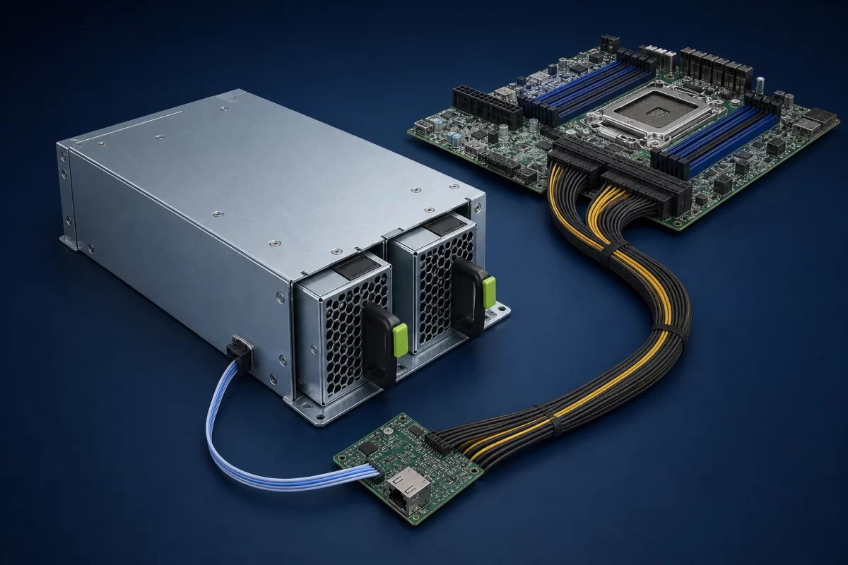
The main-current route has more interfaces than the board rating
The useful power path begins at each module’s blind-mate contacts, crosses the PDB receptacle and conductive structure, passes any combining or isolation stage, enters one or more output connectors or busbars, and continues through the harness to the motherboard or downstream distribution. Every interface contributes resistance and temperature rise. A published total-power figure therefore does not prove that every branch, connector position, or cable grouping can carry an arbitrary share of that total.
Load placement matters in multi-connector servers. A motherboard rail, accelerator zone, drive backplane, or peripheral branch may have a local limit below the PDB’s aggregate capability. Unequal cable length, connector contact condition, copper geometry, and load distribution can concentrate current. For high-current 12 V systems in particular, a seemingly small path resistance can become a meaningful voltage-drop and heating source.
The useful purchasing evidence is a supported connection map: which outputs serve which loads, the permitted current per path under the stated environment, required wire and terminal construction, and any load-balancing instruction. A total wattage claim without that map describes the assembly incompletely.
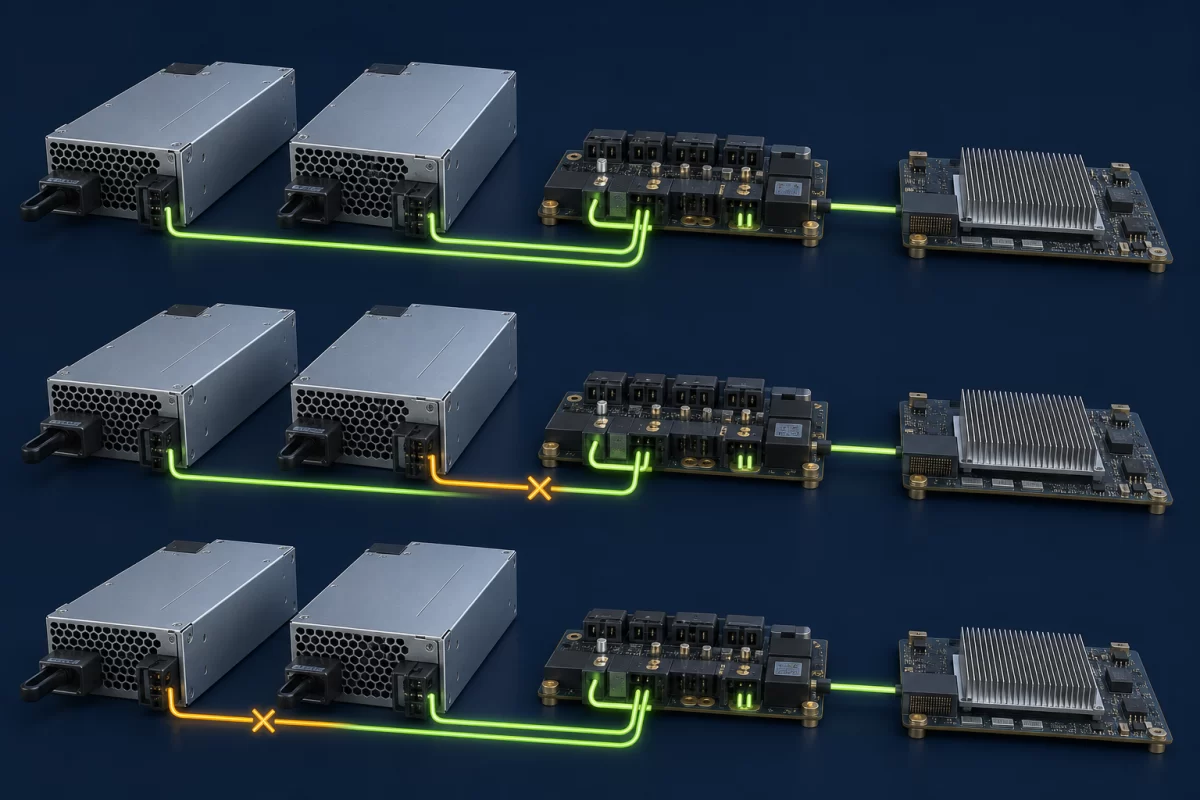
Redundancy occurs at the shared bus, not in the product name
Installing two modules gives the PDB two sources, but continuity depends on how those sources meet. Healthy supplies may share load, or a system may deliberately bias their operating points. If one module is removed or develops an output fault, the remaining path must support the permitted server load while the failed path is prevented from pulling down the shared bus.
The PDB therefore sits at a critical failure boundary. A shorted output connector, damaged combining component, common control fault, or overheated shared conductor can affect both module paths. Two CRPS units cannot protect against a fault located after their independent paths have merged. Likewise, feeding both modules from the same upstream source does not create protection from that source’s loss.
A useful CRPS PDB description separates three statements: how many modules fit, how much combined output the assembly can distribute, and what load remains supported after a defined module or feed failure. Those are related but not interchangeable claims.
Blind-mate compatibility is an interface contract
A module sliding into the cage must align mechanically and mate electrically without stressing contacts. Compatible depth, keying, guide geometry, insertion travel, latch engagement, connector position, and extraction clearance all participate. A module that looks similar from the rear may stop before full engagement or mate with an unintended interface.
Electrical agreement extends beyond the main output. Standby rail behavior, enable and power-good logic, presence detection, address selection, remote sense, current-share connection, and management pins must match the PDB and host. Differences in output setpoint or control bias can also disturb sharing even when the major dimensions appear familiar. “Common” improves the possibility of platform reuse; it should not be read as permission to mix unapproved modules.
For newer Modular Hardware System CRPS implementations, the exact specification revision and legacy relationship are especially important. Mechanical keying and electrical behavior can intentionally restrict forward or backward combinations. State the module generation and interface revision rather than relying on CRPS as the entire compatibility description.
The PDB is also a control and observability bridge
The server must know whether modules are present, healthy, sharing as expected, or operating near a limit. Depending on the implementation, the PDB can route PMBus communication and discrete signals between the supplies and the baseboard management controller. It may also provide address-selection connections so two modules can coexist on the management bus.
Physical PMBus wiring does not guarantee that the BMC understands every command, data format, status bit, or manufacturer-specific behavior. A replacement module can deliver output while producing missing telemetry or nuisance alarms. Conversely, a management problem should not be assumed to be a power-conversion failure until bus addressing, pull-ups, signal references, and firmware expectations are understood.
Ask for the supported management command set, addressing method, alarm behavior, required firmware relationship, and the server’s response to lost communication. This turns “PMBus capable” into an operational description rather than a feature label.
Host wiring determines whether the PDB is usable
Off-the-shelf CRPS PDB assemblies are often attractive for workstations, storage systems, industrial computers, and custom servers because they package redundant modules more neatly than a one-off board. The integration burden moves to the outputs. The assembly must physically mount, cables must reach without obstructing fans or service paths, and connector families and wiring must match the host.
An adapter cable cannot safely correct every mismatch. A different connector may also imply different pin assignment, current allocation, sensing point, sequencing, or motherboard power architecture. ATX-oriented hosts may expect rail and control behavior that is not reproduced simply by attaching a familiar plug. Accelerator-heavy servers may divide power among several connectors or busbars so that no single harness carries the full load.
The related server power supply distribution board design article examines copper, voltage drop, and connector loading in greater depth. For a purchased CRPS PDB, the immediate question is narrower: does the supplied output package exactly implement the host’s documented power interface?
Cooling follows the assembled installation
The CRPS fans cool the modules along their designed airflow direction; they do not automatically cool every PDB component, cable termination, or downstream connector. The carrier can shield components from chassis airflow, while cable bundles can obstruct an inlet or create recirculation. When one module is lost, the survivor’s load and fan response can change even though the PDB carries similar total server output.
Published temperature and altitude limits must be tied to the exact assembly and airflow condition. A board rating measured with defined airflow should not be transferred to a sealed compartment or a chassis with reversed flow. Temperature attention belongs at blind-mate contacts, isolation devices, high-current copper transitions, output terminals, and tightly bundled conductors—not solely at the PSU exhaust.
A complete quotation should close five boundaries
The best way to compare CRPS PDB offers is to make each boundary explicit. First is scope: list every shipped board, carrier, module, harness, and fastener. Second is module identity: record approved models, ratings, revisions, airflow direction, and permitted population. Third is host output: define connector mapping, cable construction, branch allocation, sensing, and control behavior. Fourth is redundant operation: state surviving load and the module or feed event the assembly is intended to tolerate. Fifth is management: identify signals, PMBus support, addresses, telemetry, alarms, and firmware dependencies.
These boundaries also expose whether the item belongs in the server bill of materials as a board, a mechanical subassembly, or a complete power subsystem. That classification prevents a common procurement failure: buying a technically capable PDB and discovering later that the required cage, module pairing, cable set, or BMC contract was never part of the offer.
Where a CRPS PDB product ends
A CRPS PDB product ends at the interfaces its supplier documents. Beyond that point, the server integrator owns chassis mounting, downstream wiring, load allocation, airflow, host control, and firmware behavior unless those items are explicitly supplied and supported. Treating the boundary honestly is more useful than asking whether a board is “universal.” It lets a buyer distinguish a component from an installable assembly and makes each remaining interface visible before hardware reaches the chassis.