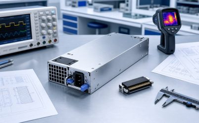
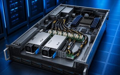
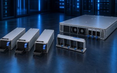
A CRPS power supply is a Common Redundant Power Supply module used in servers and related computing equipment. It converts the facility input into the server’s main DC bus and is designed to work through a defined mechanical, electrical, control, thermal, and management interface. CRPS modules are commonly installed as removable pairs or larger banks so a supported system can continue operating after one module or power path becomes unavailable. The term describes an interface family and operating architecture; it does not mean every CRPS-labeled unit is interchangeable.
Quick answer: CRPS is a module-and-system architecture
The easiest way to understand CRPS is to picture a slim, hot-pluggable converter sliding into a server and mating with a power distribution board, or PDB. The module supplies a main output, supports control and status functions, and may expose digital management data. Multiple modules can share a load and isolate a failed path when the host is designed for redundancy. Physical resemblance is not proof of compatibility: the exact envelope, output, edge connection, signals, airflow, firmware behavior, and host approval still have to align.
Follow the power path to see what CRPS actually does
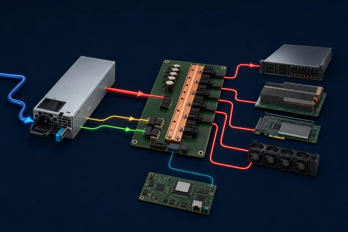
At the module inlet, an AC version receives facility power and performs the conversion stages needed to create a regulated server bus. Other input architectures also exist, so the source type must come from the exact module documentation. Inside a typical server, the main output does not directly provide every voltage used by processors, memory, storage, and fans. It reaches a PDB, motherboard, busbar, or downstream converters that distribute current and create the local rails required by each load.
A standby output can keep parts of the management and control system alive before the main rail is enabled. Control signals coordinate turn-on, report a valid output, indicate presence or faults, and support current sharing. A management connection may let the baseboard management controller read identification, voltage, current, power, temperature, status, or fault information. The exact signals and supported PMBus commands remain model- and platform-specific.
This division of labor is central to the definition. The CRPS module performs power conversion and participates in a coordinated interface. The host supplies the mating connector, distribution paths, sequencing, cooling, control logic, and firmware behavior that turn one or more modules into a server power subsystem.
The narrow module shape makes airflow part of the interface
A CRPS unit packs conversion stages, energy storage, controls, and one or more fans into a slender enclosure. Its fan must overcome the module’s internal impedance while fitting the server’s front-to-rear or rear-to-front cooling plan. The airflow direction cannot be inferred safely from the housing alone, and reversing it relative to the chassis can create recirculation or heat neighboring components.
Rated output may depend on inlet temperature, altitude, fan behavior, input voltage, and the backpressure created by the installed server. Losing one module can also alter the airflow through an empty bay or force the surviving module to dissipate more conversion heat. This is why mechanical fit and electrical output are not the entire CRPS interface: the host must provide the cooling condition under which the rating is valid. A replacement with a different fan curve or airflow direction can be unsuitable even if it powers up on a bench.
Four operating moments reveal the redundant behavior
During standby and startup, auxiliary power and control logic establish the conditions for the main output to turn on. Once the server is running with two active modules, the pair may share current. The sharing method matters because a severely unbalanced pair can place one unit near its limit while the other appears lightly loaded. Some supported platforms can use a cold-redundancy strategy that keeps reserve modules in a reduced-power state and activates them when needed.
If one module or input is lost, isolation in the module and PDB should prevent the faulted path from pulling down the shared bus. The healthy module receives the load, provided its available output covers the server’s permitted continuous and transient demand under the deployed input, temperature, and airflow conditions. An alarm or management event should identify the degraded state.
During an authorized hot-swap replacement, the system continues on the surviving capacity while the failed unit is withdrawn. The incoming module must mate in the intended sequence and control inrush so it does not disturb the live bus. After it becomes valid, current sharing and telemetry return to the supported normal state. Hot swap is therefore a behavior of the connector, PDB, module, controls, and service procedure—not merely a removable handle.

Why “common” does not mean universally interchangeable
CRPS specifications were created to establish common interface patterns for server power modules, but implementations, revisions, ratings, and host requirements vary. Two units can look nearly identical yet differ in depth, keying, airflow direction, output behavior, contact assignment, standby capability, control timing, PMBus implementation, firmware identity, or operating limits. A module that slides into a bay can still be electrically or logically wrong for that server.
Interchangeability requires agreement across several boundaries at once. The chassis must accept the full mechanical envelope and extraction path. The card edge must align with the host connector and use the expected contact functions. The PDB must support the current, isolation, sensing, and sequencing behavior. The BMC must tolerate or recognize the module’s identification and management responses. The server manufacturer may restrict supported combinations even when basic electrical operation appears possible.
The word common is useful because it narrows the design space and supports modular system development. It should not be read as permission to substitute an unapproved module. Powernexu’s standard CRPS compatibility article examines that substitution boundary in more depth.
CRPS, ATX, and power shelves solve different packaging problems
| Architecture | Power-delivery role | Typical service model | Interface emphasis |
|---|---|---|---|
| CRPS module | Feeds a server bus through a host PDB or mating interface | Designed for modular replacement when the host permits it | Blind-mate mechanics, sharing, status, management, and redundancy coordination |
| ATX-style PSU | Provides several familiar computer rails and cabled outputs | Often requires equipment shutdown for replacement | Motherboard and peripheral cable interfaces |
| External power shelf | Converts power for multiple chassis or a high-power rack bus | Modules may be serviced independently of compute trays | Shelf controller, busbar or cable distribution, and rack-level capacity |
This comparison describes architectural tendencies, not universal rules. Redundant ATX-derived assemblies exist, and CRPS modules can be used in more than one system arrangement. The practical distinction is where conversion, distribution, redundancy, and service boundaries sit. CRPS places a compact replaceable converter at the server interface; a shelf moves conversion into a shared rack-level assembly.
CRPS does not create redundancy by itself
A server with one CRPS module has a modular power source but no module redundancy. A two-module server is 1+1 only when either module can support the allowed load after the other is lost. If both ratings must be added to carry normal demand, the system has combined capacity at that load rather than full single-module protection.
Upstream wiring also determines the protected failure set. Two modules connected to one branch can tolerate some module failures while remaining exposed to that branch, PDU, or source. Connecting the modules to appropriately independent A and B paths extends coverage, subject to the actual facility architecture. The PDB must then maintain isolation and carry the transferred current without excessive voltage drop or temperature rise.
For a deeper treatment of surviving capacity and isolation, see the CRPS redundant power architecture article. The important definitional point is that CRPS enables a structured redundant design; the module label alone does not prove the completed system’s fault tolerance.
What M-CRPS adds to the terminology
Modern server documentation may use M-CRPS, referring to Modular Hardware System Common Redundant Power Supply work published through the Open Compute Project. It continues the idea of a modular, managed, redundant power interface while addressing newer platform requirements and form factors. A buyer should treat “CRPS” and “M-CRPS” as related specification contexts, not casually collapse every generation into one interchangeable pool.
The exact revision matters because server architectures are changing. Dense accelerator platforms may use higher-voltage distribution and separate power domains, while conventional enterprise servers may retain a familiar server bus. Power ratings, source options, mechanical lengths, cooling arrangements, and management expectations can change across generations. Current host documentation should identify which module family and combinations are supported.
The module label is only the beginning of identification
A useful CRPS identity includes the manufacturer part number, hardware and firmware revision, rated input conditions, output rating and derating, airflow direction, efficiency certification where applicable, mechanical drawing, connector definition, supported control and management behavior, and host approval. Matching only wattage is especially risky: two equal-wattage modules may implement different interfaces, and a higher-wattage replacement may exceed a PDB or connector limit.
The CRPS power supply specification reference organizes those fields for readers who need to evaluate a particular unit. For someone asking only what CRPS means, the essential idea is simpler: it is a coordinated replaceable server power module whose useful behavior emerges only when its interface matches the host system.
Where the term CRPS stops
CRPS identifies an architecture for common, modular, redundant server power—not a complete compatibility guarantee, a redundancy certificate, or a universal pinout. It explains why the supply is slim and removable, why it mates to a PDB, why current sharing and fault isolation matter, and why the BMC may communicate with it. The exact module documentation and server support list define the remaining boundary. That distinction lets designers gain the serviceability and standardization benefits of CRPS without treating a shared name as proof that two modules can safely replace each other.