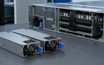
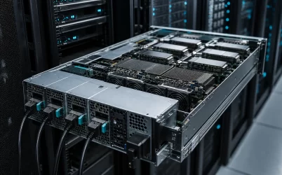
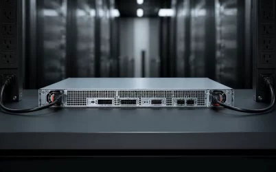
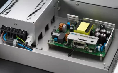
A 2U server power supply should be selected as part of the chassis layout, not as an isolated wattage number. The extra vertical space in a 2U enclosure can support larger fans, more storage, accelerator cards, and redundant power modules, but those elements compete for the same rear-panel area and airflow. A sound design therefore starts by mapping the PSU envelope, inlet and exhaust paths, power-distribution interface, service clearance, and the load that must remain supported after the intended failure condition.
Start with the rear-panel map
The two rack units provide more packaging freedom than a 1U server, yet the usable power-supply volume is still constrained by PCIe slots, network interfaces, fan walls, drive backplanes, and cable exits. Decide early whether the modules will be stacked vertically, arranged side by side, or connected through a power distribution board. That decision affects connector access, hot-swap travel, and how much exhaust area remains open.
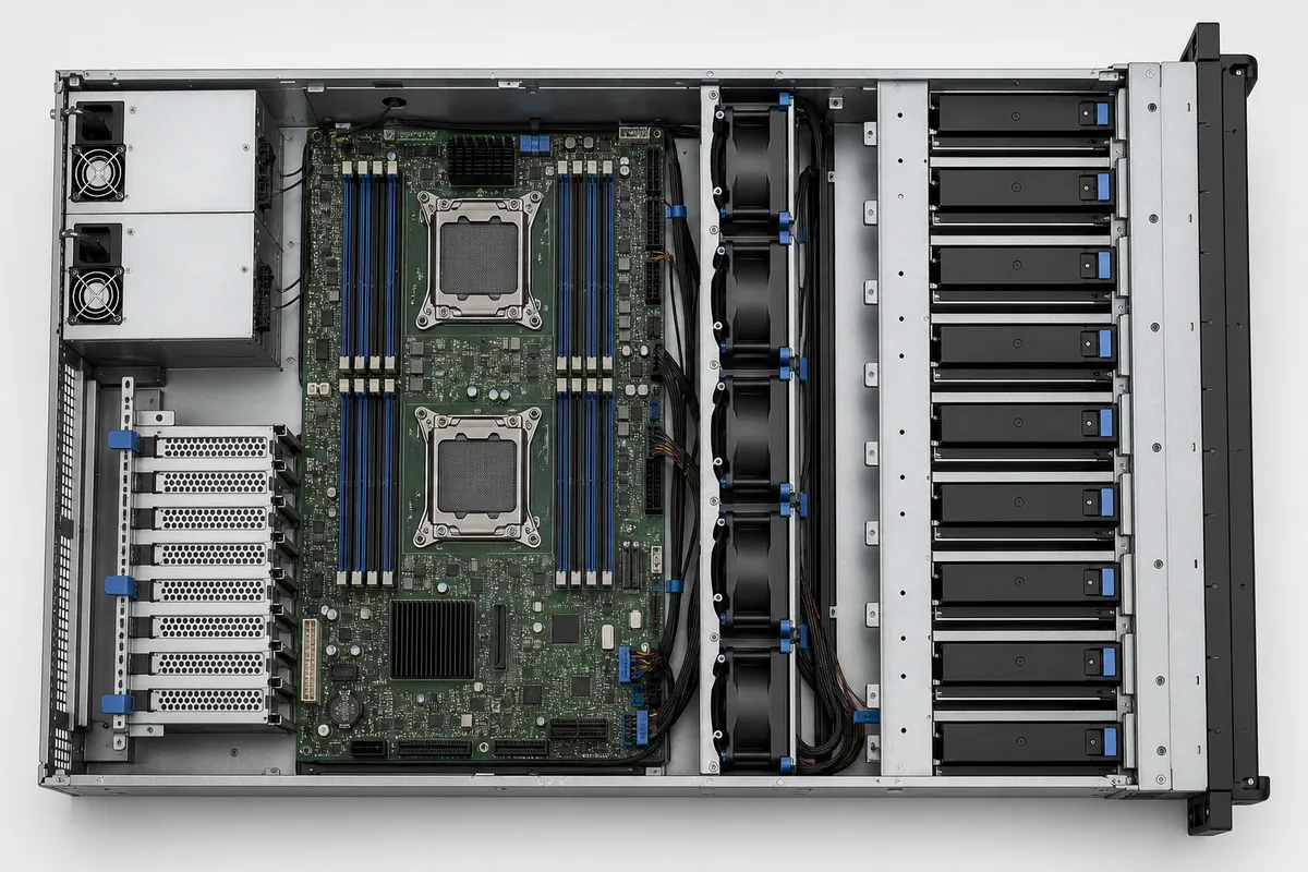
A layout drawing should include more than the metal outline. Record the insertion path, handle movement, mating depth, cable bend radius, neighboring component height, and the space a technician needs to remove a module without disturbing network or accelerator cabling. A mechanically compatible unit can still be impractical if its extraction path is blocked after the server is fully populated.
Translate the system inventory into a power envelope
Build the load estimate from the actual configuration: processors, memory, storage, fans, controllers, accelerators, motherboard conversion losses, and auxiliary rails. Nameplate values are useful boundaries, but telemetry from representative workloads gives a better view of sustained demand and short peaks. Include fan power at the highest expected operating condition because fan consumption rises just when thermal margin is under pressure.
Consider a hypothetical 2U compute node with an 820 W sustained DC load and a 1,020 W measured short-duration peak. If the architecture is 1+1 redundant, either installed module must be able to carry the required load alone after its partner is removed or fails. Two modules rated only to share 820 W in normal operation would not provide true one-module fault tolerance. The selection must also respect the module’s input-voltage range, ambient-temperature derating, and transient capability; the arithmetic alone is not sufficient.
| Design input | Question to answer | Layout consequence |
|---|---|---|
| Normal and peak load | Can one module support the required failure state? | Module count, rating, and PDB current path |
| Expansion plan | Will GPUs, NICs, or drives be added later? | Reserve output, connectors, and cooling capacity |
| AC environment | What input voltage and branch limits apply? | Usable output and facility compatibility |
| Service model | Must replacement occur while the node runs? | Hot-swap access and retention design |
Airflow is a shared chassis resource
PSU airflow cannot be evaluated independently from the server fan wall. Recirculation near the rear, cable bundles across an inlet, or mismatched airflow direction can raise local inlet temperature even when the rack room is within its target range. The thermal review should follow the air from the rack inlet through drives, processors, memory and accelerators, then through or around the power modules.
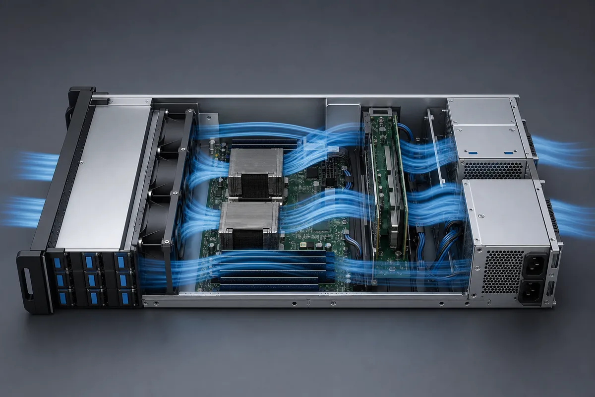
Larger 2U fans may move the required air at a lower rotational speed than very small blowers, but only when the pressure path is well controlled. Test the worst intended drive and card population, blocked-filter condition if filters are used, elevated inlet temperature, and the single-PSU operating state. Verify module inlet temperature rather than relying only on room or rack sensors.
Choose the electrical architecture before choosing connectors
A 12 V distribution architecture remains common, while higher-voltage intermediate buses can reduce current for the same transferred power. The appropriate approach depends on the motherboard, accelerator topology, conversion stages, and available ecosystem. For example, a 1,200 W load at 12 V corresponds to 100 A before allowing for distribution losses. The same power at 48 V corresponds to 25 A. This does not make one architecture universally superior: higher-voltage systems move conversion and protection requirements elsewhere in the design.
The PSU output connector, PDB copper, busbars, board-to-board contacts, and downstream wiring must be treated as one current path. Confirm mating compatibility, current sharing, presence detection, enable sequencing, auxiliary power, and any management signals from verified interface documentation. Physical fit does not establish electrical compatibility.
Design redundancy around the failure state
Configurations described as 1+1 normally use two modules so one can carry the specified system requirement if the other becomes unavailable. A 2+0 arrangement may use both modules for capacity without preserving operation after one module is lost. Firmware labels and marketing shorthand should not replace a documented fault-state analysis.
During a module loss, the surviving supply and distribution network must accept the load step without an unacceptable bus excursion. Current sharing under steady operation matters because a persistent imbalance can increase temperature and age one unit faster. Hot-swap behavior also depends on connector sequencing, inrush control, ORing or isolation elements, and system firmware. Engineers comparing architectures can use the related explanation of server redundant power paths as a companion reference.
Validate the populated 2U system
Qualification should use the server configuration that creates the most demanding combination of electrical load and airflow restriction. Exercise cold start, warm restart, workload transitions, AC interruption behavior, one-module removal, reinsertion, fan response, alarms, and telemetry. Inspect connector and PDB temperatures at stable high load and after repeated service cycles.
The final procurement record should lock the mechanical revision, interface definition, firmware expectations, approved input conditions, airflow direction, and redundancy mode. This turns the PSU from a nominally interchangeable part into a controlled subsystem. For a 2U platform, that discipline preserves the enclosure’s main advantage: enough space to balance expansion, cooling, power capacity, and serviceability rather than optimizing one at the expense of the others.