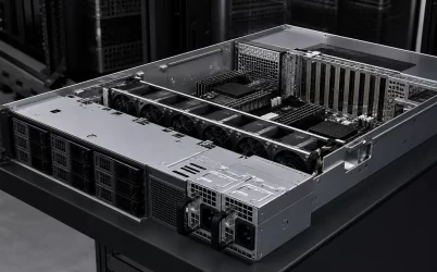
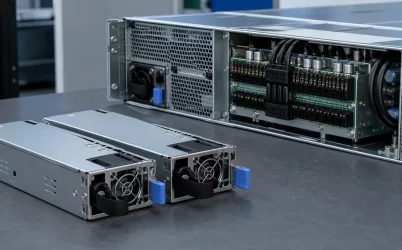
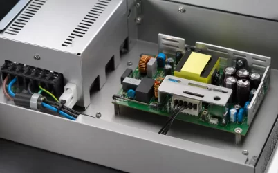
A 1U redundant power supply design succeeds only if the server remains stable when one module stops contributing. That failure instant is more important than the combined wattage printed on two installed supplies. In a compact 1U chassis, the surviving module, power distribution path, fan system, and controls must absorb the transition while operating within tight thermal and mechanical limits. Qualification should therefore begin with a single-module-loss scenario and work backward to module rating, airflow, connector layout, and service procedure.
The first second after a module is lost
Before the event, two supplies may share the load. When one is removed, loses AC, or shuts down for protection, isolation elements should prevent the healthy bus from feeding the failed path. The surviving module accepts additional current, the output bus experiences a transient, alarms change state, and cooling behavior may adjust. The platform must keep its critical rails inside their allowed limits throughout that sequence.
This is a system behavior, not a PSU-only property. Connector sequencing, ORing devices, PDB impedance, stored energy, control-loop response, firmware delays, and downstream converters all influence the result. Test the actual server rather than relying on the sum of catalog ratings.
Inside the 1U mechanical envelope
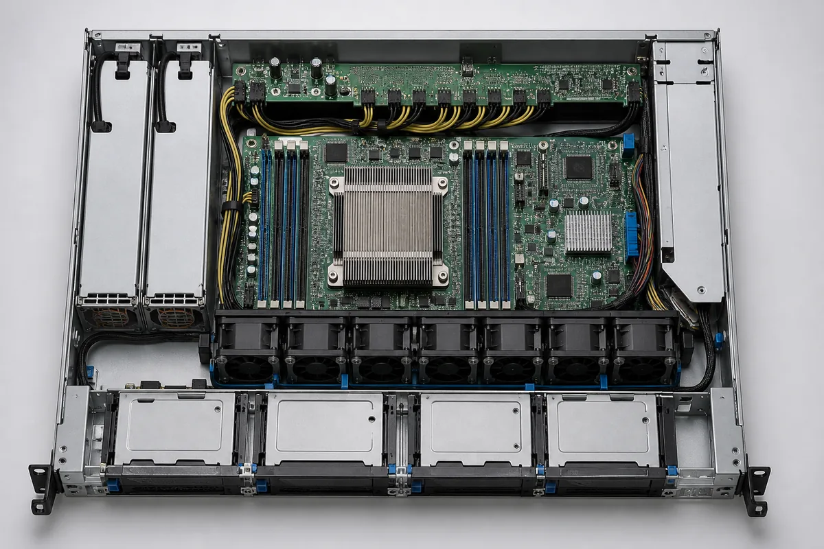
One rack unit leaves limited height for magnetic components, heatsinks, fans, handles, and high-current contacts. The PSU bay also competes with motherboard area, drive bays, fan modules, and rear I/O. Small changes to chassis sheet metal or PDB location can affect mating depth and airflow resistance.
Check module outline, insertion rails, latch clearance, connector location, airflow direction, and removal space. Include tolerances and cable movement. A technician should be able to identify and replace the failed module without pulling the healthy one or blocking its inlet. Mechanical interchangeability must be verified by drawing and fit test, not by the “1U” label.
Size for the survivor
Suppose a hypothetical 1U server consumes 720 W at its qualified sustained workload and reaches an 840 W short peak. If the requirement is continued operation after either PSU is removed, the surviving module must support the defined post-fault demand under the applicable AC input and inlet temperature. Installing two 500 W units could provide 1,000 W of aggregate capacity in a nonredundant operating mode, but it would not preserve a 720 W workload after one unit is lost.
Define whether the server must maintain full performance after failure or may enter a documented reduced-power state. If throttling is part of the design, validate its detection time and the energy available before it takes effect. Also account for temperature and input-voltage derating from verified module data.
Current sharing is also a thermal issue
With both modules healthy, balanced sharing can reduce stress and heat concentration. Exact equality is not normally expected, but persistent large imbalance deserves investigation because one module may operate hotter and accumulate more aging. Sharing depends on compatible modules, connection resistance, control implementation, and sometimes firmware configuration.
Measure input and output telemetry where available and confirm it with suitable instruments during qualification. Compare module inlet temperatures as well as power. In a 1U rear zone, an adjacent cable bundle or fan obstruction can make two nominally identical supplies experience different cooling conditions.
Hot swap must be rehearsed
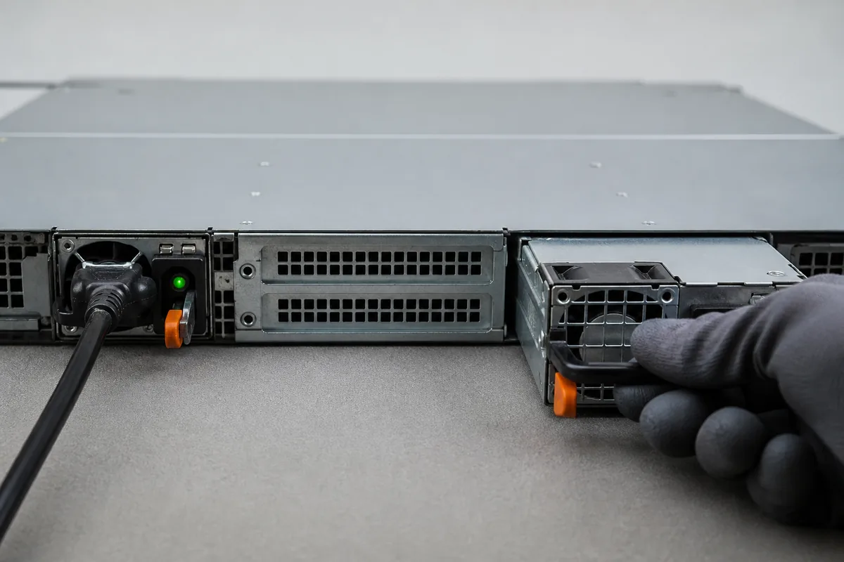
- Confirm the failed module from indicators and management data, and verify the healthy module is carrying the server within its qualified envelope.
- Remove AC from the intended module if the platform procedure requires it, then release and extract the module without disturbing the neighboring supply.
- Inspect the replacement part and interface revision before insertion.
- Insert and latch the module according to the server procedure, restore its input, and observe sharing, alarms, fan behavior, and telemetry.
- Record the event and confirm that redundancy has returned rather than assuming an illuminated indicator proves complete recovery.
The exact service sequence is platform-specific. Follow the server manufacturer’s supported procedure and safety requirements. The rehearsal is valuable because it reveals labeling ambiguity, blocked extraction paths, excessive connector force, and management delays before they occur during an outage.
Faults that deserve separate tests
- Loss of AC to one module: verifies transfer behavior without mechanical removal.
- Module extraction: exercises connector sequencing and service handling.
- Reinsertion at load: checks inrush, isolation, and return to current sharing.
- Blocked or degraded cooling: evaluates temperature response and alarms.
- Communication loss: confirms the server handles missing telemetry without confusing it with loss of output.
Protection functions such as overvoltage, overcurrent, overtemperature, and short-circuit response vary by design. Verify their system interaction from qualified documentation and testing; do not assume every fault results in the same latching or retry behavior. The related article on CRPS redundant power integration covers interface and qualification considerations for standardized module ecosystems.
Release criteria for a compact redundant server
A 1U platform is ready when it passes the intended load and thermal cases with both modules, with either single module, through removal and reinsertion, and across supported input conditions. The release record should identify approved module revisions, PDB and firmware versions, airflow direction, power policy, and alarm behavior.
That evidence prevents a common mistake: treating redundancy as the presence of two PSUs. Real redundancy is a verified operating state in which one defined fault can occur, the server continues as intended, the fault is visible, and service restores protection without disrupting the workload.