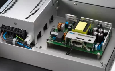
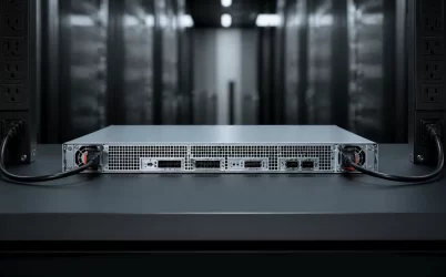
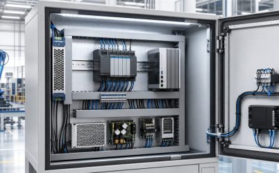
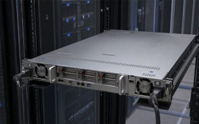
A rack server power supply should be selected from the server’s measured power demand, redundancy requirement, chassis height, airflow, AC source, and management interface. The correct rating is the capacity available after the defined failure, not the combined wattage printed on every installed PSU. For 1U and 2U servers, mechanical envelope and cooling impedance can be as important as electrical output. A compatible design must also coordinate the PSU with the cage, PDB, connectors, BMC, rack PDU, cords, and facility feed.
Quick Answer
Start with the maximum sustained server load, include qualified configuration growth, and verify that the surviving PSU or PSUs can carry it after one module or one feed is lost. Then check input-voltage derating, transient response, connector current, current sharing, efficiency across the normal load range, airflow direction, acoustic limits, hot-swap behavior, and PMBus/BMC support. Do not purchase by wattage and physical appearance alone; rack-server PSU compatibility must be confirmed for the exact chassis and firmware.
1U and 2U Chassis Create Different Constraints
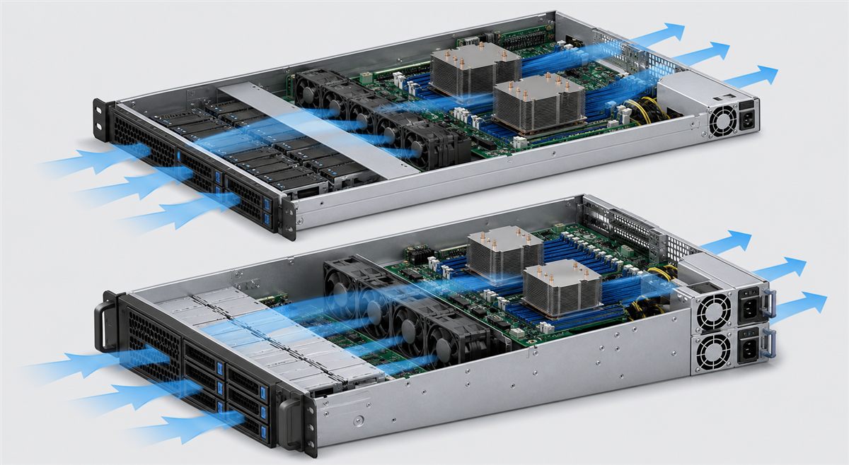
A 1U server places processors, memory, storage, fans, expansion devices, and power conversion in a very shallow airflow channel. PSU height and width are tightly constrained, and a small increase in airflow impedance can affect fan power and component temperature. Cable bends, risers, and rear I/O can also restrict the available PSU bay.
A 2U chassis offers more layout freedom and can accept larger fans or additional modules, but it may also carry more accelerators, drives, or processors. More physical space does not necessarily mean a lower power density. Selection should therefore use the actual platform configuration rather than a rule that treats all 1U or all 2U servers alike.
Calculate Failure-State Capacity
Assume a dual-socket rack server reaches a measured 980 W DC under its maximum qualified workload. Adding 15% for configuration growth and operating variation gives 1,127 W. In a 1+1 redundant design, each PSU must deliver at least 1,127 W at the deployed AC input and inlet temperature. Two 1,200 W modules meet the nameplate calculation, but the remaining 73 W margin is small; transient, thermal, and input-voltage tests determine whether the choice is robust.
If both modules normally share the load, each carries about 564 W in this example. When one fails, the other moves immediately to approximately 1,127 W. The rack PDU outlet, cord, inlet, blind-mate connector, PDB, and cooling system must all tolerate that state.
Redundancy Extends Beyond the PSU Pair
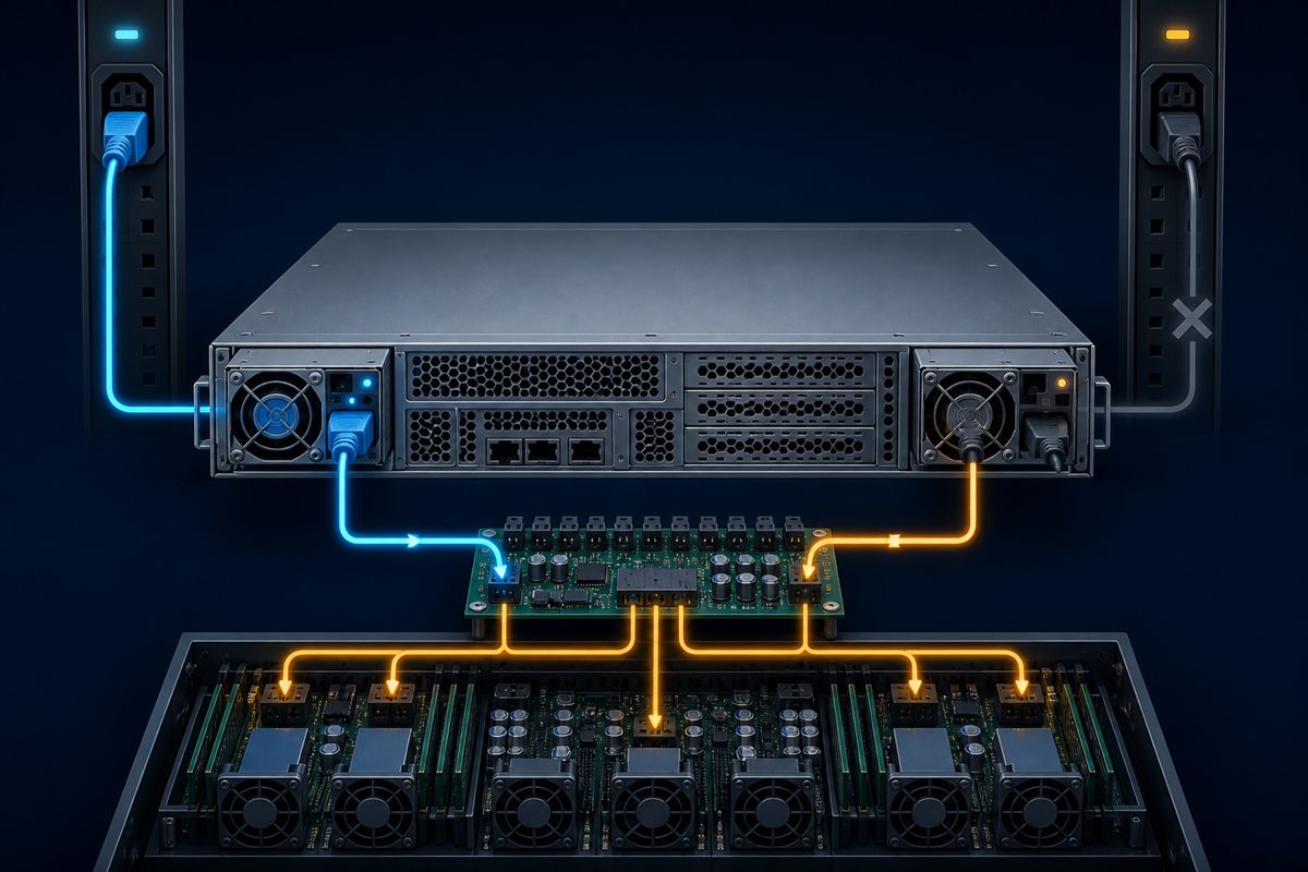
Two PSUs connected to one rack PDU are protected against a module failure but not against the loss of that PDU or upstream branch. A true A/B design connects each PSU to an independent path where the availability objective requires it. Those paths may converge farther upstream, so the boundary of redundancy should be documented.
| Architecture | Benefit | Important limitation |
|---|---|---|
| Single PSU | Lowest component cost and space | PSU failure generally stops the server |
| 1+1 on one feed | Module redundancy and hot replacement | Upstream feed remains a common point |
| 1+1 on A/B feeds | Protects against one PSU or one independent feed loss | Each path must carry the full server load |
| N+1 multi-module | Scales to higher loads | Requires stable sharing and correct failure-state capacity |
Efficiency, Heat, and Rack-Level Power
PSU loss becomes heat inside the data hall. At 1,000 W DC output, 94% efficiency requires about 1,064 W AC and produces about 64 W of loss. At 90%, input rises to about 1,111 W and loss to about 111 W. Across forty servers, the difference is roughly 1.9 kW of additional electrical load and almost the same additional heat to remove.
Peak efficiency is not enough. Measure or obtain data at the loads created by the redundancy policy. If two modules share a light server load, each may operate far below its most efficient point. Supported cold-redundancy modes can change this, but the transfer behavior and platform firmware must be qualified.
Electrical, Thermal, and Management Checks
- Confirm output rating at the actual AC voltage, frequency, temperature, and altitude.
- Verify current sharing and output stability from idle through peak workload.
- Check startup, hold-up, protection, and recovery with the exact PDB and server load.
- Measure PSU, connector, and adjacent-component temperatures in the final chassis.
- Validate airflow direction and avoid mixing modules with incompatible fan behavior.
- Confirm PMBus addressing, telemetry, FRU data, alarms, and BMC firmware support.
- Test hot removal, hot insertion, and loss of each A/B source at maximum qualified load.
Questions to Ask Before Approval
Can a higher-wattage PSU replace a lower-wattage module?
Only if the platform explicitly supports it. Higher wattage does not prove mechanical, connector, signal, firmware, thermal, or current-sharing compatibility.
Should both redundant PSUs be identical?
Matching qualified part numbers and firmware is the safest default. Mixed operation should be used only when the server manufacturer documents and validates the combination.
Does hot swap guarantee uninterrupted service?
No. The remaining power path must have enough capacity, the failed module must isolate correctly, and the server must tolerate the electrical transition.
For related server-level architecture decisions, see server power supply architecture. Qualification should finish with evidence from the exact production chassis, not only a bench load.