An open frame switching power supply is a complete power-conversion assembly supplied without a protective outer enclosure. That construction can deliver high integration density and give an equipment designer direct control over mounting, airflow, connectors, and cable routing. It also transfers responsibilities to the host product: protection from hazardous energy, creepage and clearance around the board, grounding, mechanical support, thermal management, EMC filtering and shielding, contamination control, and regulatory evaluation. Selection is therefore an enclosure-design task, not simply a search for a board with the desired voltage and wattage.
The enclosure becomes part of the power supply
An enclosed supply arrives with metalwork, guarded terminals, and a more defined airflow environment. An open frame unit relies on the equipment chassis to prevent unintended contact and to maintain required separation from conductive panels, fasteners, wiring, and other boards. Covers, barriers, insulating sheets, standoffs, and access controls may be needed according to the product’s safety design.
Begin with the supplier’s installation drawing and safety notes. Mark hazardous primary-side areas, isolation boundary, mounting holes, component height, underside clearance, connector access, and required free space. Then overlay the host chassis, wiring, ventilation, and service zones. This exercise often reveals conflicts long before the first prototype.
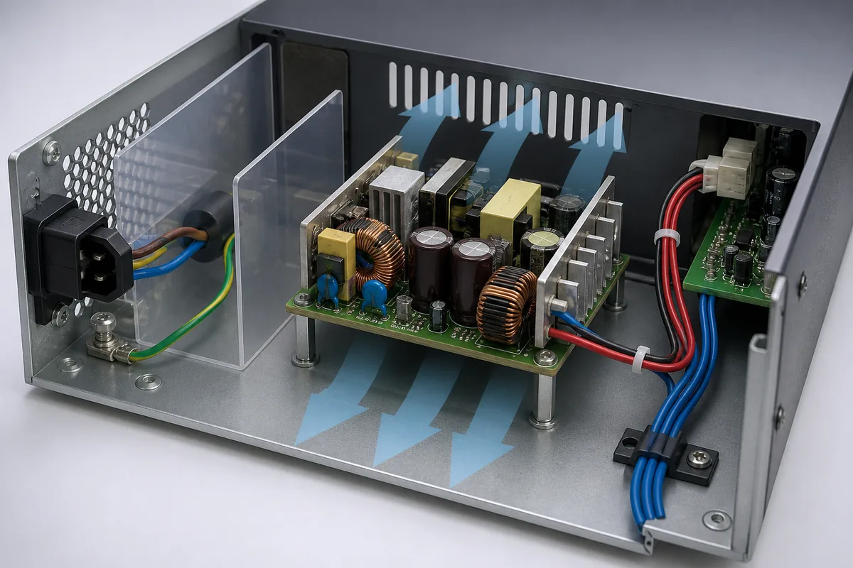
Mounting hardware can compromise electrical spacing
Standoffs should support the board without bending it and should be located only at approved mounting points. Conductive hardware near the primary circuit can reduce clearance or create a fault path. Screw heads, washers, and chassis features must remain outside required spacing through manufacturing tolerance and vibration. If insulating supports are used, their material, temperature capability, flammability, and mechanical strength matter.
The board should not depend on connectors or heavy components for structural support. Transformers, inductors, and heat sinks add mass that can stress the PCB under shock and vibration. Cable pull should be restrained by the chassis. Service access must prevent tools from slipping into energized areas.
Airflow ratings depend on direction and measurement conditions
Open frame datasheets may provide different output ratings for natural convection and forced air. A forced-air rating normally assumes a stated airflow magnitude, direction, and measurement location. A nearby fan’s nominal airflow in free air does not prove that the required air crosses the hot components after filters, grilles, cables, and other boards add impedance.
Use the derating curves for ambient temperature, input voltage, altitude, and cooling. Identify the specified temperature reference point. Measure component or designated case temperatures in the production enclosure after thermal equilibrium. Test low line because higher input current can increase stress in the input stage, and test high line where switching behavior may shift.
Layout should guide air across actual loss centers
Heat is concentrated in semiconductors, magnetics, rectifiers, heat sinks, and sometimes current-sense or input components. Arrange the board so incoming cool air reaches these zones without recirculating exhaust. Tall components can shadow shorter ones. A cover placed close above the board may create a narrow channel that improves directed flow or traps heat, depending on inlet and outlet geometry.
Thermal imaging helps locate hot spots, but shiny heat sinks and small components can produce misleading readings. Attach sensors at supplier-specified points when limits are critical. Evaluate blocked filters, reduced fan speed, and expected dust accumulation if those are credible operating states.
Input wiring begins the EMC design
Switching converters draw high-frequency current and generate common-mode and differential-mode noise. Keep input and output wiring separated, minimize loop area, and avoid routing sensitive signal cables close to switching nodes or magnetics. Protective earth and functional earth should follow the supplier and system safety architecture. A metal chassis can provide shielding only when seams, bonding, and apertures are designed effectively.
An internal EMI filter may help a component meet its stated test condition, but the finished product changes cable lengths, grounding, enclosure, load, and nearby electronics. Conducted and radiated emissions must be assessed at system level. Immunity to surge, electrical fast transients, electrostatic discharge, and RF fields also depends on the host’s ports and grounding.

Safety spacing extends beyond the PCB
The power-supply PCB may maintain its internal creepage and clearance, while installation introduces a grounded panel, cable shield, metal fastener, or another board too close to a hazardous node. Required spacing depends on voltage, insulation system, pollution environment, material group, altitude, and applicable standard. Use qualified safety engineering for the target product rather than applying a generic distance.
Prevent user and service access to hazardous voltages. Ventilation openings may require evaluation with accessibility probes. Stored energy can remain after input removal, so discharge time and warning or service procedures may be relevant. Fuses, disconnects, protective earth, and branch protection must be coordinated with the equipment design.
Load behavior determines whether the board starts reliably
List continuous demand and startup events for every output. Motors, solenoids, heaters, lamps, batteries, and capacitive loads can produce overload or inrush. The supply’s response may be constant current, foldback, hiccup, or shutdown. If it repeatedly restarts into a heavy capacitive load, the equipment can remain trapped in a boot cycle.
Multiple-output models may specify minimum load, cross-regulation, sequencing, or a combined-power limit. Remote-sense leads have compensation and routing limits. Adding external capacitance or an output filter can interact with control stability. Use the supplier’s permitted ranges and test the real load harness.
Choose the output at the worst operating corner
Do not select from nominal room-temperature power alone. Determine usable output at minimum input, maximum enclosure temperature, altitude, and available airflow. Add load growth only when it is credible; excessive oversizing can move normal operation into a light-load region with different efficiency or regulation behavior.
Voltage drop occurs in connectors, wiring, fuses, switches, and distribution boards. Measure at the load during peak current. If the load has a narrow tolerance, allocate an error budget across supply regulation, ripple, transient deviation, distribution loss, temperature drift, and measurement uncertainty.
Protection functions need a host-level response
Overvoltage, overcurrent, short-circuit, and overtemperature protection can reduce damage, but their thresholds and recovery policies differ. Decide whether the equipment should retry, remain off, signal a fault, or require operator action. A power-supply protection feature does not replace correct branch fusing, wire sizing, enclosure grounding, or load-specific safety controls.
If the supply is paralleled or used redundantly, review current sharing and reverse-current isolation. Ordinary outputs should not be tied together without manufacturer support or a designed ORing stage. The remaining source must carry the intended load after one unit fails.
Component approvals do not certify the finished product
A recognized or certified open frame supply can simplify the equipment approval process because its construction and isolation have been evaluated within a defined scope. The host still needs assessment for mounting, accessibility, temperatures, spacings, wiring, protective devices, EMC, and application-specific requirements. Medical, industrial, information-technology, and household equipment can impose different expectations.
Retain certificates, reports, conditions of acceptability, and exact model identity. Confirm that markings and approval references cover the purchased variant. A later board revision or alternate component should follow the supplier’s controlled approval process.
Prototype tests that reveal integration problems
- Inspect mounting, underside clearance, primary-side spacing, barriers, earth bonding, and connector access.
- Apply minimum and maximum input and measure startup, inrush, output timing, and steady regulation.
- Exercise realistic load steps, startup loads, overload, short circuit, and recovery.
- Run thermal tests at worst load, input, temperature, orientation, airflow, and altitude condition.
- Measure ripple with the specified probing method and voltage at the remote load.
- Conduct pre-compliance emissions and immunity tests using production-equivalent cables and enclosure panels.
- Evaluate abnormal airflow, fan fault, blocked vent, wiring fault, and service states required by the product plan.
- Repeat relevant checks after changes to chassis, fan, filter, cable routing, grounding, or load.
The tests should use documented acceptance limits. A prototype that “keeps running” may still exceed a component temperature, noise limit, safety spacing, or rail tolerance.
When open frame is the right architecture
Open frame construction fits equipment whose manufacturer controls the enclosure and needs compact integration, custom airflow, or direct board-level connections. An enclosed or U-channel supply can reduce integration work when touch protection, mechanical guarding, and a more self-contained thermal path are priorities. The best choice depends on product volume, certification plan, engineering resources, service model, contamination, and packaging.
Powernexu’s AC/DC open frame power supply article covers selection in a broader application context. For projects comparing industrial form factors, the industrial power supply selection guide provides additional decision factors.
Integration questions
Can an open frame supply be operated without an enclosure?
It may be powered in a controlled qualified laboratory setup, but end use normally requires protection, spacing, mounting, cooling, and safety measures provided by the host equipment. Follow the supplier’s installation conditions.
Does adding a fan automatically unlock the forced-air rating?
No. The required airflow must reach the specified components in the specified direction and condition. System impedance and recirculation can make fan free-air ratings misleading.
Is an internal EMI filter enough for product compliance?
Not necessarily. The enclosure, grounding, cables, ports, and load alter emissions and immunity. The complete equipment needs evaluation against its applicable requirements.
Can the PCB be mounted directly to a metal base?
Only using the approved mounting points, standoffs, spacing, and insulation arrangement. A metal surface too close to the underside can violate electrical clearance or create a fault hazard.