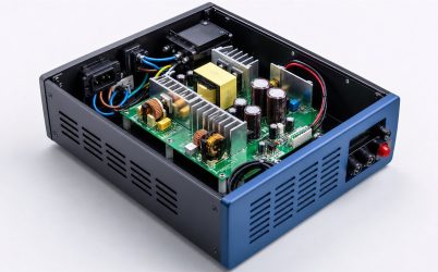
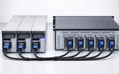
Power supply redundancy is the deliberate addition of power paths so a defined load remains energized after a specified source or module failure. The core design question is not “How many supplies are installed?” but “Which failures can occur while enough isolated capacity remains?” A 1+1 pair may cover one failed converter. An N+1 bank may support a larger shared load. Separate A/B inputs can extend protection upstream. ORing prevents a failed output from pulling down healthy sources, while monitoring exposes the degraded state. This article provides a design method that applies to servers, networking, telecom, industrial controls, and other continuous-operation equipment.
Step 1: write the continuity requirement as an event
“High availability” is not precise enough. State events such as: the load must remain within its DC voltage limits after any one PSU module fails; operation must continue after either input branch is de-energized; one module must be replaceable while the load remains active; or scheduled maintenance on one source must not interrupt service. Each statement produces a different architecture and test.
Also define exclusions. A single downstream short, common control-board failure, simultaneous source loss, or multiple module failure may fall outside the requirement. Honest boundaries allow investment to target the failures that matter rather than implying universal fault tolerance.
Step 2: choose capacity notation that matches the load
In 1+1 redundancy, either of two supplies can carry the required load. In N+1, N supplies provide the necessary capacity and one additional unit provides reserve. A three-module system may be 2+1 when two modules are required for the load. A 2N design duplicates the full required capacity in two groups, often to align with independent power chains.
Installed wattage is not the same as redundant capacity. If two 1,000 W supplies feed a 1,500 W load, both are needed; the system cannot lose one without reducing load. If the required load is 800 W and one module can provide that power under deployed conditions, the pair may operate as 1+1. Use the derated rating at real input voltage, temperature, altitude, and airflow.
Step 3: map failure domains from source to load
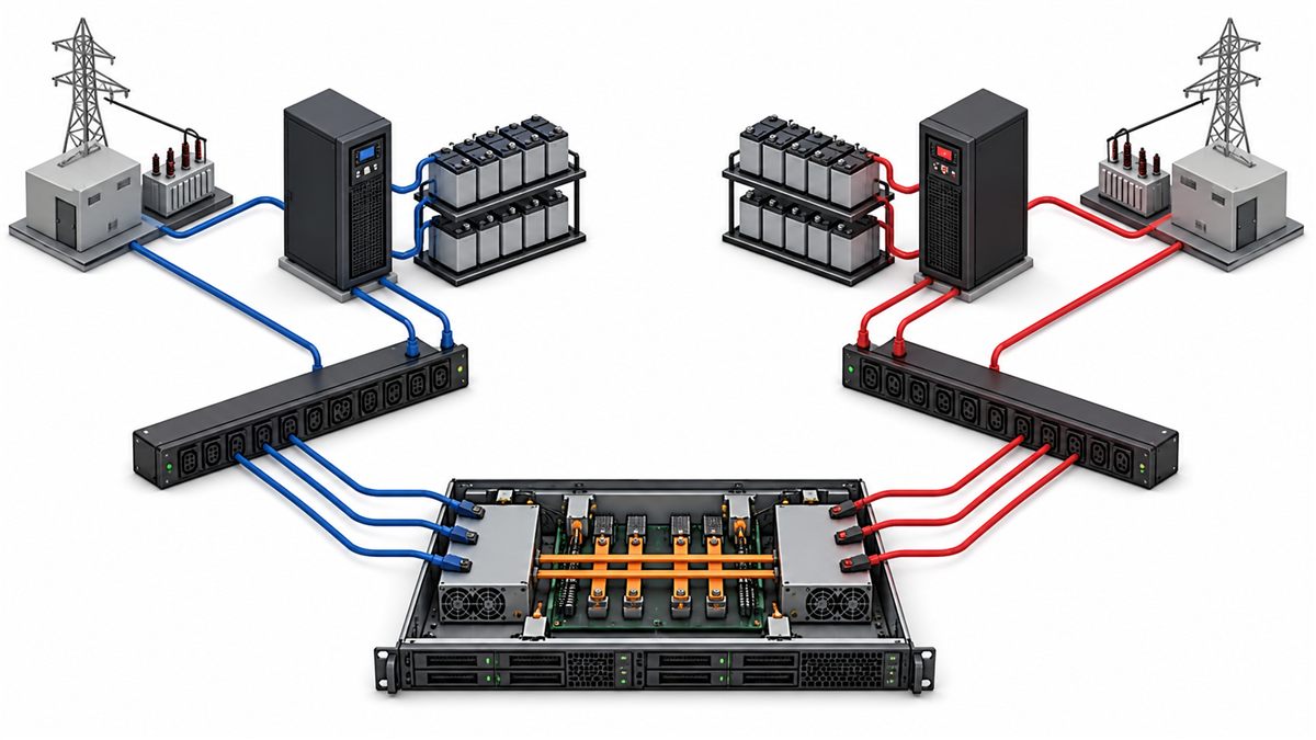
Trace utility or generator, UPS, switchgear, branch circuit, PDU, cord, input connector, PSU, isolation device, distribution board, cable, and load. Mark components shared by all paths. Two supplies on one input branch protect against some converter failures but not branch loss. Two feeds that join at one unprotected distribution stage share that stage.
The map also supports maintenance planning. If source A is taken out of service, source B must carry the complete load without exceeding branch, PDU, connector, or PSU limits. Normal balanced current can conceal inadequate failover capacity. Measure and alarm on each path separately where practical.
Step 4: prevent reverse current and fault propagation
Outputs cannot usually be tied together safely without a supported parallel or ORing architecture. Small set-point differences can make one source carry most of the current. If one output shorts, it can sink current from the others and collapse the bus. Diodes provide simple reverse-current isolation at the cost of forward voltage and heat. MOSFET-based ideal-diode circuits reduce loss but add control and failure-mode considerations.
Locate the isolation boundary deliberately. It may be internal to each module, implemented in a separate redundancy module, or placed on a PDB. Rate it for normal sharing, single-path current, transient transfer, reverse voltage, and thermal conditions. Analyze open and short failures of the isolation components themselves.
Step 5: decide how healthy modules share load
Active current-share interfaces can balance output, but compatibility and allowed imbalance are model-specific. Passive droop sharing is another approach in some systems. Without a designed method, one supply may carry nearly all current because its set point is slightly higher. That defeats thermal balance and can cause unexpected shutdown.
Redundant efficiency may improve when fewer modules carry load, so some platforms place reserve modules in standby. That strategy needs controlled transitions and sufficiently fast response. It should be implemented only when the modules and system controller support it. Sharing mode affects energy, component temperature, fan operation, and how facility feeds are loaded.
Step 6: include dynamic demand in surviving capacity
The load transferred after failure includes fast events, not just an average. Servers can have CPU or accelerator excursions; industrial systems may start motors or solenoids; telecom loads can change with traffic. Characterize peak magnitude, duration, slew rate, repetition, and acceptable voltage deviation. The survivor and distribution network must respond before slower controls can reduce demand.
Stored energy can bridge short transitions, but adding capacitance affects startup, inrush, fault energy, and stability. If load shedding or a power cap is part of the architecture, state its response time and the load classes it disconnects. Do not count on software response unless it is faster and more dependable than the electrical event it is intended to manage.
Step 7: design live replacement only when it adds value
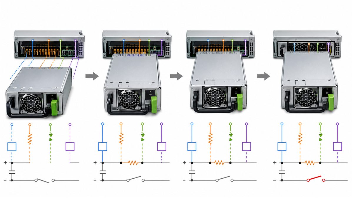
Hot swap allows a failed module to be replaced without de-energizing the load. It requires sequenced contacts, inrush control, output isolation, mechanical alignment, and a procedure that prevents removal of the healthy path. Redundancy provides the capacity during service; hot-swap design makes the connection event safe and controlled.
Some industrial systems use fixed supplies where repair occurs during planned downtime. In that case, hot-swap complexity may not be justified even though redundant operation is valuable. Architecture should follow the maintenance objective rather than assuming every redundant supply needs a removable cartridge.
Step 8: make degradation visible
A redundant system can hide a failure because the load continues to operate. Without monitoring, it may run for months with no reserve. Use module status, input presence, output current, temperature, fault contacts, local indicators, management telemetry, and remote alarms as appropriate. Alarm logic should distinguish a failed converter from loss of its upstream input.
Define alert ownership and response time. A facility team may own the branch circuit while an equipment team owns the module. Event logs and timestamps help relate upstream and downstream alarms. Periodic tests should confirm that notifications reach the responsible person and clear correctly after restoration.
Step 9: calculate the penalty and value
Redundancy adds capital cost, volume, wiring, isolation loss, controls, spares, and maintenance. Active modules may operate at lower load fractions where efficiency differs. Conversely, avoided downtime can be far more valuable than these costs. A total-cost discussion should include the probability and consequence of target failures, service response, energy loss, cooling, rack or cabinet space, and the life of the system.
Do not use a universal formula for all applications. A control system protecting a continuous industrial process has different consequences from a development server. A network node with dual facility feeds has a different risk profile from remote equipment on one utility branch. The redundancy class should match the operational loss it is designed to prevent.
Architecture comparison
| Architecture | Strength | Limitation to examine |
|---|---|---|
| Two supplies, one shared input | Can tolerate selected module faults | Shared branch remains a single point |
| 1+1 with A/B inputs | Can cover one module or input-path loss | Common distribution and load remain |
| N+1 module bank | Efficient capacity scaling for larger loads | One reserve may not cover an entire source group |
| 2N power chains | Duplicates required capacity across paths | Higher cost, space, and operational complexity |
| Redundant supplies with hot swap | Restores reserve without planned shutdown | Requires compatible live-mating system and procedure |
The rows are not mutually exclusive. A system may use N+1 modules within each side of a larger architecture. The appropriate description should specify both capacity and source arrangement.
Qualification proves the claimed fault tolerance
- Measure the load profile and establish the maximum redundant load.
- Run each source path independently at input and thermal extremes.
- Interrupt one module and one input path at a time while monitoring the load bus.
- Test representative load transients immediately before and after transfer.
- Observe current sharing, reverse current, isolation, connector, and thermal behavior.
- Exercise supported removal and insertion sequences for hot-swap designs.
- Inject defined alarms and verify local indication, remote notification, and logs.
- Restore the path and confirm stable sharing, cleared alarms, and renewed reserve.
Repeat critical tests after changes to supply model, firmware, redundancy controller, distribution board, wiring, airflow, load, or upstream source. Record conditions and acceptance limits so the claim is reproducible.
Design errors that turn redundancy into false confidence
- Adding module ratings even though one must carry the load after failure
- Connecting both inputs to one branch while claiming source redundancy
- Paralleling unsupported outputs without current sharing or reverse isolation
- Ignoring low-line, temperature, altitude, and airflow derating
- Sizing from average demand while omitting transient load
- Allowing degraded operation without an actionable alarm
- Assuming removable means hot swappable
- Using an unqualified replacement because voltage and wattage look similar
Powernexu’s dual redundant server power supply article applies these principles to server systems. For common modular server interfaces, the CRPS redundancy integration guide covers module, PDB, and management coordination.
Questions about redundancy design
Does N+1 mean one extra supply regardless of load?
It means N modules provide required capacity and one additional module supplies reserve, all under the defined operating conditions. The value of N changes with load and each module’s usable output.
Are redundant supplies always active?
No. Some share load continuously, while supported systems may place a reserve unit in standby for efficiency. Transition behavior and fault response must be designed for the chosen mode.
Can redundancy eliminate the need for a UPS?
Not generally. Redundant converters protect against selected module or input-path faults. A UPS addresses source interruption and power-quality objectives. The functions can complement each other but are not interchangeable.
How often should failover be tested?
The interval should follow risk, equipment guidance, change frequency, and maintenance policy. Tests are especially important after hardware, firmware, wiring, airflow, or load changes that could alter transfer behavior.