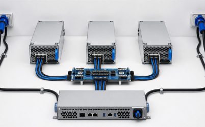
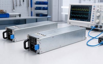
N+1 redundant power supply architecture keeps a load operating after any one required power module becomes unavailable. The letter N represents the number of healthy modules needed to carry the permitted load; the “+1” is reserve capacity. A three-module bank is therefore 2+1 only when two modules can support the load under the deployed input, temperature, airflow, and transient conditions. Counting installed wattage without applying that surviving-capacity rule creates false redundancy. This article develops N+1 as a failure-domain and capacity problem, showing how load limits, current sharing, output isolation, source grouping, and maintenance policy fit together.
The capacity equation behind N+1
Let each module have usable output P under the worst supported operating condition. If N modules are required, the permitted redundant load cannot exceed N multiplied by P, with any additional platform limits applied. The installed bank contains N+1 modules, but its redundant capacity is based on N. For example, three identical modules with 1,000 W usable output can form a 2+1 bank for a load up to 2,000 W, subject to transient, distribution, and thermal limits. It should not be advertised as 3,000 W redundant capacity.
“Usable” is deliberate. A label rating may be available only over a higher AC input range or below a stated inlet temperature. Altitude and airflow can reduce output. Connector, PDB, busbar, or branch limits may be lower than the sum of module ratings. Establish P from the complete supported envelope rather than a favorable laboratory point.
Why N changes as the load grows
N is not a permanent property of the chassis. It depends on the active load. A four-module platform might be 2+1 with one additional unused slot at a moderate configuration, 3+1 after accelerators are added, or nonredundant if the load eventually requires all four modules. Capacity management should recalculate the redundancy state after CPU, GPU, storage, memory, fan, or firmware power-limit changes.
Slow average telemetry can understate the requirement. Processor turbo, accelerator excursions, motor starting, or radio transmit bursts may demand rapid current. The N healthy modules must keep the bus within tolerance during credible peaks after one module is lost. If supported load shedding or a power cap participates, its guaranteed response time must be faster than the electrical collapse it is intended to prevent.
N+1 does not automatically provide source redundancy
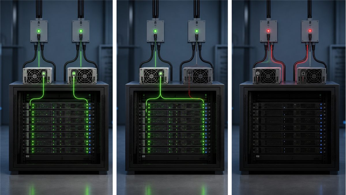
All N+1 modules can be connected to one branch, PDU, rectifier input, or upstream source. That arrangement may tolerate one module failure but will not survive loss of the common input. If the continuity requirement includes source failure, divide modules across appropriately independent A and B feeds and calculate whether the remaining feed group contains enough usable capacity.
Grouping can change the answer. A six-module system configured as 5+1 has one spare module, yet a 3-and-3 split across A and B cannot lose an entire feed while sustaining a load that needs five modules. Source-redundant capacity may require a 3+3 or another arrangement in which either input group carries the target load. State module redundancy and feed redundancy separately.
Current sharing keeps the reserve meaningful
Healthy active modules need a supported method to distribute current. Active share buses, droop sharing, or platform control may be used. Perfect equality is not expected, but excessive imbalance can place one unit at its current or thermal limit while others retain unused capacity. Measure individual output and temperature across light, typical, and maximum load.
Some systems keep the +1 module active; others place reserve capacity in standby for efficiency. Standby strategies require coordinated PSU and system support because the reserve must wake and assume load rapidly after a failure. They also affect input-feed balance and component operating hours. The chosen mode should be explicit in both energy and failover analysis.
ORing stops one failed output from becoming a common fault
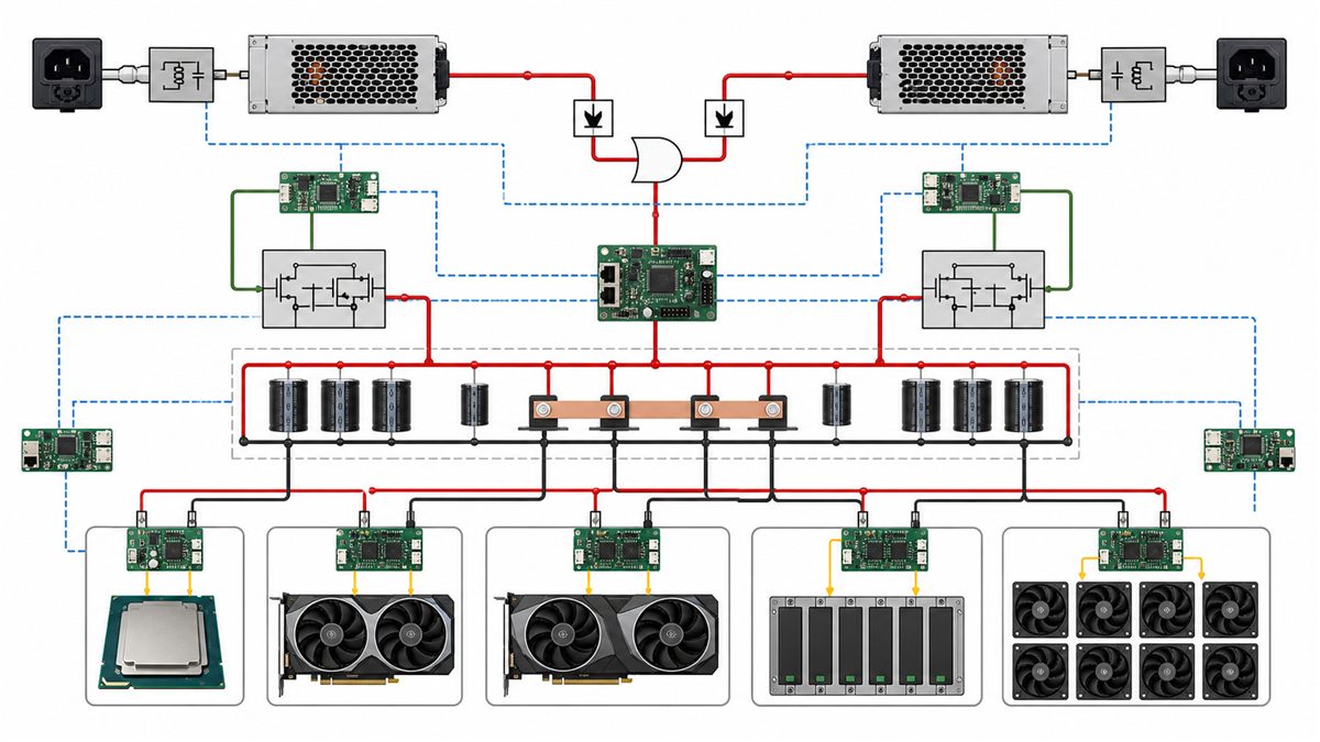
Parallel outputs require reverse-current isolation. A module that loses input or develops an output short must not sink current from the healthy bank. Diodes or controlled MOSFET ORing stages can provide this function inside modules, on a distribution board, or in a separate redundancy assembly. Their voltage drop, current rating, thermal design, and failure behavior affect the system.
Isolation devices carry more current after a module is lost. A path that runs cool in the N+1 state may become the thermal limit in the N state. Qualification should inspect connectors, copper, shunts, ORing devices, and cables after temperatures stabilize at maximum redundant load.
Failure-domain analysis reveals what the extra module cannot cover
Draw the chain from each input source through protection, wiring, module, isolation, distribution, and load. An N+1 bank still has common elements: output bus, PDB, enclosure cooling, controller, or downstream converter. One extra module does not protect against every common failure. The architecture claim should name the single events it is designed to tolerate.
| Event | N+1 can maintain operation when | Remaining concern |
|---|---|---|
| One module stops producing output | N healthy modules retain sufficient capacity | Faulted output must be isolated |
| One module is removed | Live removal is supported and N modules carry the load | Airflow and insertion sequence |
| One input branch fails | The surviving feed group has N capacity | Upstream independence |
| Shared PDB faults | Only if the PDB itself has separated redundant paths | Common bus and control remain |
| Load exceeds N capacity | Only if supported load shedding acts in time | Transient response and policy |
Module count should follow maintenance strategy
N+1 provides time to repair a single failed module without stopping the load. The length of that degraded window depends on the consequence of a second failure, spare availability, access, and thermal capability. Remote sites may need more reserve or a longer autonomous period than staffed data centers. A system with easy hot replacement can restore reserve quickly, while a fixed industrial installation may wait for a planned outage.
Hot swap is not implied by N+1 notation. Live replacement needs an approved connector sequence, inrush control, output isolation, mechanical guidance, and operating procedure. If modules are fixed, the system can remain redundant in operation but still require shutdown for repair.
Efficiency trade-offs depend on active module count
Sharing load across N+1 active modules places each at a lower fraction of rating than using N modules. Efficiency curves often change with operating point. A standby-reserve policy can reduce fixed losses, but switching reserve states adds control requirements and may concentrate facility load on one input group. Compare energy using actual per-module curves and hours in each mode.
Conversion loss also becomes heat. Adding a module adds fan, control, and conversion losses even when lightly loaded. Conversely, spreading current can reduce conduction loss and component temperature. The outcome is design-specific; standardized efficiency certification and manufacturer curves provide inputs, while system measurements show the deployed result.
Commissioning an N+1 bank
Commissioning should also establish alarm thresholds before full-load operation. A warning based only on total bus power can miss one overloaded module or a failed reserve unit. Compare individual module current, input status, fan condition, and temperature. Where management telemetry is available, reconcile it with external measurements and record expected tolerances. The degraded-state alarm should remain active until reserve capacity is genuinely restored, including successful module identification and stable current sharing.
- Measure or bound sustained and transient demand for the final load configuration.
- Determine each module’s usable output at deployed input, temperature, altitude, and airflow.
- Set the redundant load limit at or below the capacity of N healthy modules and the distribution path.
- Run the system with each individual module disabled or removed in turn.
- Observe bus voltage, module current, current sharing, input transfer, and temperature.
- Test the supported fault isolation, alarm, and recovery behavior.
- Exercise hot removal and insertion only when the platform explicitly supports it.
- Verify that monitoring identifies degraded operation and that the response team receives the alert.
The tests should be repeated after changes to module model, firmware, share controller, PDB, input grouping, cooling, or load. A previously valid 2+1 configuration can become nonredundant after a hardware upgrade.
Using N+1 in server, telecom, and industrial systems
Rack servers and blade platforms may use modular AC/DC supplies feeding a shared low-voltage bus. Telecom plants often parallel rectifier modules on a DC bus with battery support. Industrial systems can combine DIN-rail or chassis supplies through a redundancy module. The electrical principle is similar, but connector, control, safety, grounding, battery, and service requirements differ. Avoid transferring one industry’s implementation details into another without qualification.
For server-specific A/B feed behavior, Powernexu’s dual redundant server power supply architecture provides a complementary view. The broader power supply redundancy design method compares N+1 with 1+1 and 2N approaches.
The final design decision
Capacity records should show the assumed load, module derating, distribution limit, source grouping, and the event that removes the reserve. Operations can then compare live telemetry with the approved boundary. When expansion pushes demand above that boundary, the response is a deliberate capacity upgrade or a revised continuity target—not an unnoticed loss of N+1 protection.
N+1 is appropriate when the system must tolerate one module loss and the remaining N modules, inputs, isolation devices, distribution network, and cooling can carry the permitted load. If the requirement includes loss of an entire source group, the module arrangement must also preserve N capacity on the surviving feed. The most useful specification is therefore not “contains N+1 PSUs,” but a statement such as: “The system supports the defined maximum load after any one PSU module is removed under the stated input and environmental conditions.” That statement can be tested, monitored, and maintained.