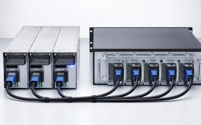
A 2200W PMBus redundant server power supply is not adequately specified by three labels—2200W, PMBus, and redundant. The 2200W output may depend on input voltage and cooling; PMBus may expose only a subset of commands; and redundant operation depends on the mating PDB, current-share method, isolation, and surviving-module load. A useful purchasing specification therefore treats the unit as an electrical source, a managed device, and one half of a fault-tolerant power path. This reference explains the evidence needed in each layer without inventing a pinout or assuming that similar CRPS modules are interchangeable.
The commercial description must be converted into acceptance clauses
The first clause should identify the exact manufacturer part number, hardware revision, firmware revision, mechanical option, airflow direction, input connector, and certification records. The next should state the conditions under which 2200W is continuously available: input range, inlet temperature, altitude, and required airflow. A third should name the host interface, including PDB, connector drawing, control signals, current share, and PMBus expectations.
This approach prevents an offered module from passing because it matches only headline wattage. It also gives procurement a controlled basis for substitutions. An alternate should satisfy the same clauses or return to engineering review.
2200W output begins with the facility input
High-power server modules frequently have input-dependent output ratings. The full 2200W may be available only over a stated higher-voltage region, while low-line operation is derated. Use the manufacturer’s exact curve for the proposed unit. Record maximum input current, frequency, inrush, power factor, leakage, and hold-up conditions so the rack PDU, cord, inlet, branch protection, UPS, and generator interface can be assessed.
For 1+1 redundancy, a single module must support the permitted server load after its companion is lost. If the deployed input permits less than 2200W, the redundant server limit must use that lower value. The pair’s labels must not be added when either module is expected to carry the complete load.
Translate the server workload into a 2200W operating envelope
List sustained demand for processors, memory, storage, accelerators, fans, and motherboard conversion, then characterize boot and workload excursions. A 2200W rating is a continuous ceiling under stated conditions; it does not define transient response. Request load-step magnitude, slew rate, voltage deviation, recovery, overload duration, and current-limit behavior where these are material to the host.
Management telemetry normally updates more slowly than the fastest electrical events. Oscilloscope or high-speed acquisition data is needed during qualification. PMBus readings remain valuable for operating trends and alarms, but they should not be treated as proof that every sub-millisecond excursion stayed within the bus tolerance.
PMBus is a command contract, not a checkbox
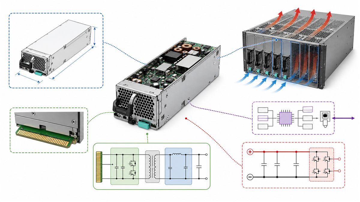
PMBus support can include input voltage and power, output voltage and current, temperature, fan speed, warning and fault status, manufacturer identification, capability data, and control. The implemented command set varies. Obtain a command matrix for the exact firmware, including pages, data formats, scaling, accuracy, update rate, warning limits, fault bits, and any manufacturer-specific commands.
The current PMBus organization page lists revision 1.5 as the current published specification, but a power supply may implement an earlier revision or a defined subset. Compatibility follows the module and BMC contract, not the newest revision number by itself. The official PMBus current specifications page is the appropriate source for revision status.
Addressing and bus behavior affect dual-module service
Two installed modules must appear at supported addresses without conflict. Address pins, slot decoding, PDB routing, or host logic may participate. Define pull-up voltage, bus capacitance, connector sequencing, timeout, and recovery from a missing or stuck device. Live removal can interrupt a transaction; the BMC should recover communication with the healthy module and identify the absent bay.
After replacement, the host should read identity, firmware, capability, and status before treating redundancy as restored. An electrically active unit that is rejected by platform policy may leave persistent alarms or disable a power-management mode. This is one reason a physically compatible high-power module can still be an unsupported replacement.
Telemetry accuracy determines how the data can be used
Monitoring input power for capacity planning needs a different accuracy expectation from detecting a gross fault. Request accuracy and resolution across the relevant load and temperature range. Compare reported input and output values with calibrated external instruments during qualification. Account for update interval and averaging when relating readings to workload behavior.
Do not use an unqualified PMBus value as the sole protection mechanism. Hardware current limit and platform power controls operate on different timescales. Telemetry can support alerting, energy analysis, load balancing, and diagnosis once its limitations are known.
Redundant operation requires a compatible PDB
The blind-mate connector can carry high-current output and return contacts, standby power, remote sense, enable, power-good, presence, fault, current share, address, and communication. Use the exact module and PDB pin definitions. Similar form factor does not establish identical contact assignment, mating sequence, or signal polarity.
The PDB must carry full single-module current, isolate a faulted output, and distribute power to downstream loads without excessive voltage drop or temperature rise. Connector and copper limits can be lower than the PSU rating. A 2200W replacement does not upgrade the PDB automatically.
Current sharing should be evaluated as a pair
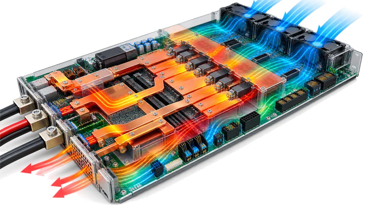
With both modules active, share control should keep imbalance within the supported range. Differences in output set point, firmware, temperature, or share implementation can make one unit carry more load. Record individual current and temperature at light, typical, and high server demand. Repeat at input and thermal extremes.
Some platforms support an efficiency or hot-spare mode that concentrates load on one module. This requires coordinated PSU, PDB, and BMC behavior. The standby module must assume load within the platform limit, and facility A/B feeds must tolerate the transfer. Mixing revisions can invalidate the mode even if steady output appears normal.
Fault isolation defines the meaning of redundancy
ORing diodes or controlled MOSFET stages prevent an unpowered or shorted module from pulling down the shared bus. Their location may be inside the PSU or on the PDB. Review reverse-current behavior, short-circuit response, overvoltage, overcurrent, overtemperature, fan fault, and recovery. A list of protection abbreviations without thresholds and response modes is not enough.
The BMC should distinguish loss of input from an internal module fault where supported. It should report loss of redundancy promptly because the server can continue operating with no reserve. Alarm clearing should occur only after the replacement is healthy, sharing is stable, and management communication has returned.
Mechanical and airflow variants can look deceptively similar
Compare height, width, depth, connector datum, guide features, latch, handle travel, keying, and extraction clearance. Confirm the airflow direction and fan-control policy. A reverse-airflow version can oppose the server cooling path. A deeper module may enter the rear opening but collide internally or fail to seat against the PDB.
At 2200W output, even a small conversion loss produces meaningful heat. Use the exact efficiency curve and thermal derating, then test the production chassis at maximum inlet temperature. Include the single-module state, when the survivor carries all power and an empty bay can change pressure and recirculation.
The minimum supplier data package
Request that each document carry a revision and exact applicable part number. Conflicting values should be resolved before release, especially when a marketing sheet, mechanical drawing, and PMBus file were issued at different times. The acceptance package should also identify which options are mandatory for the target host and which are merely available in the wider product family.
| Document | Decision it supports |
|---|---|
| Datasheet and derating curves | Available 2200W output by input and environment |
| Mechanical drawing | Bay, connector, latch, and extraction fit |
| Connector and signal definition | Safe PDB electrical interface |
| PMBus command matrix | BMC telemetry, status, addressing, and control |
| Efficiency and certification evidence | Energy and compliance review for the exact model |
| Protection and timing data | Fault response, startup, power-good, and recovery |
| Host qualification evidence | Supported operation with the target platform |
A staged host qualification
- Inspect model identity, revision, drawing, connector, and input conditions before energizing.
- Power the standby domain and read identity, capability, status, and supported commands.
- Enable the main output at controlled load and compare telemetry with external measurements.
- Exercise startup, shutdown, steady load, dynamic load, and maximum supported output.
- Measure temperatures at the PSU inlet, exhaust, connector, PDB, and isolation devices.
- Run each module alone at the permitted redundant load.
- Interrupt each input, remove and insert each approved module, and capture the shared bus.
- Review PMBus warnings, BMC events, local indicators, current-share recovery, and alarm clearance.
Powernexu’s CRPS power supply specification checklist provides further interface detail. The server PDB design article explains why distribution limits remain important at high current.
The release decision
The release record should preserve the tested module and firmware revisions, host BMC version, PDB revision, input voltage, chassis airflow, workload limit, and PMBus command results. This baseline makes later substitutions auditable. If any of those interfaces changes, engineering can identify the affected tests instead of assuming the original approval still applies unchanged.
A 2200W PMBus redundant server power supply is ready for release when the exact offered revision delivers the required output at the deployed input and environment, fits and mates with the approved PDB, implements the BMC’s required command contract, shares and isolates faults correctly, and carries the server alone within the redundant limit. Anything less leaves one of the three headline claims—2200W, PMBus, or redundancy—unsupported in the actual host.