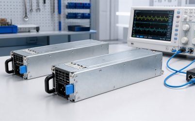
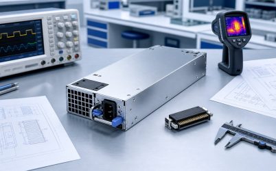
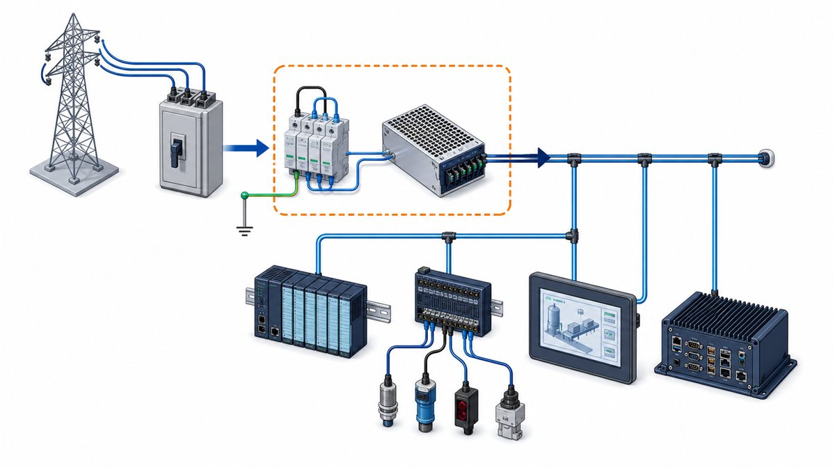
An industrial AC-DC power supply converts facility alternating current into the regulated DC used by controllers, industrial computers, sensors, communication equipment, relays, and actuators. The decisive selection inputs are not a generic “industrial” label but the real mains environment, load events, enclosure temperature, contamination, grounding, and required response to faults. A supply that delivers the nominal voltage on a bench can still reset a controller during a brownout, enter current limit when a valve starts, or overheat inside a sealed cabinet. This guide follows energy from the AC branch to the DC load and identifies the decisions at each boundary.
Characterize the incoming AC environment
Record minimum and maximum voltage, frequency, expected dips, interruptions, surges, and source type. Utility mains, generators, UPS outputs, and long plant feeders can present different impedance and waveform behavior. The supply’s specified range must cover normal operation, while the equipment design should define what happens outside that range.
Input current, inrush, leakage, and power factor affect the branch circuit. Several supplies energized together can trip protection even when steady current is acceptable. Coordinate fuses or breakers, disconnects, conductor size, protective earth, and surge protection with applicable installation requirements.
Build a time-based DC load profile
Separate continuous loads from events. PLCs and sensors may be stable, while relays, solenoids, fans, motors, heaters, and capacitive converters can produce startup peaks. Record magnitude, duration, repetition, and which events can overlap. Average current does not reveal whether the supply will enter foldback, hiccup, constant-current, or shutdown behavior.
Review the overload curve rather than assuming spare wattage covers every peak. Long cable runs add voltage drop at the moment current is highest. Measure the rail at the load and use remote sense only within the manufacturer’s permitted compensation and routing conditions.
Derating defines usable output inside the cabinet
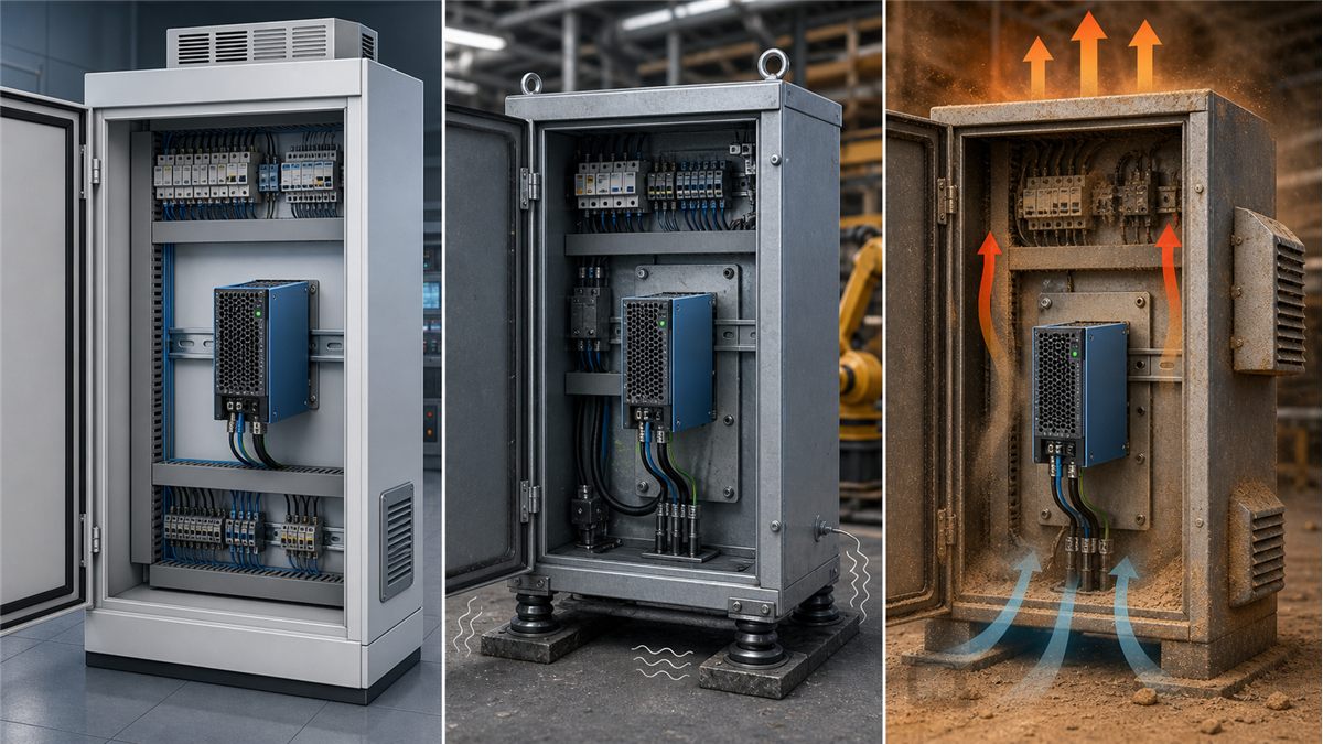
The relevant temperature is usually near the supply or at its inlet, not the room thermostat. Drives, contactors, computers, and neighboring converters raise cabinet temperature. Apply the documented derating curve at maximum ambient, minimum input, altitude, orientation, and actual airflow.
Fanless equipment still requires a heat path. Convection-cooled units need spacing and orientation; baseplate-cooled units need a controlled mechanical interface; fan-cooled units need clean inlet and exhaust routes. Filters and dust accumulation should be included in the maintenance condition.
Plan for contamination and mechanical stress
Dust can block airflow or insulate hot components. Conductive particles, moisture, condensation, oil mist, and corrosive gases can create leakage and corrosion. Vibration stresses transformers, capacitors, terminals, and solder joints. The response may involve an enclosed supply, coating, filtered cabinet, sealed housing, different connectors, or equipment documented for the environment.
Mounting should support the unit without distorting it and leave access to terminals, status indicators, fuses, and removal hardware. Separate hazardous input wiring from low-voltage and signal cables as required. Provide strain relief so field wiring does not load terminals.
Translate output quality into equipment behavior
Set-point tolerance, line regulation, load regulation, ripple, temperature drift, and transient deviation combine at the load. A processor can reset during a short dip even when average voltage is correct. A sensor interface may respond to high-frequency noise. Compare the load’s permitted envelope with the supply and distribution budget.
Measurement method matters. Ripple specifications commonly define bandwidth, probe connection, and local capacitance. Adding large external capacitance without review can increase inrush, extend discharge, and affect control-loop stability. Follow the documented capacitive-load range.
Grounding and EMC belong to the finished machine
Protective earth, functional earth, chassis bonding, cable shields, and DC return need an intentional architecture. Switching current loops can couple noise into analog, encoder, and communication cables. Keep input, output, and sensitive signal routing controlled, and bond metalwork according to the equipment safety and EMC plan.
A component-level approval or filter supports system design but does not certify the completed machine. Production-equivalent cable lengths, enclosure panels, grounding, ports, and load activity should be present during emissions and immunity evaluation.
Input ride-through should match process tolerance
A short mains dip does not have the same consequence in every machine. Some controllers must remain active long enough to preserve state and command a controlled stop. Other equipment can restart after a brief interruption without process risk. Hold-up time is normally specified at defined input and load conditions, so it should be compared with the actual undervoltage event and the minimum DC voltage accepted by the load.
If longer ride-through is required, a DC UPS, battery-backed bus, or larger system energy store may be appropriate. Extra capacitance on the output should not be added casually: it changes charging current, discharge time, fault energy, and startup behavior. The energy-storage solution should include safe isolation, monitoring, maintenance, and end-of-life planning.
Multiple rails require sequencing and a shared power budget
Industrial equipment can need 24 V for controls, 12 V for computers, 5 V for logic, or isolated rails for instruments. These may come from one multi-output AC-DC supply or from downstream DC-DC converters. A multi-output datasheet can specify combined-power limits, minimum load, cross-regulation, or output-specific derating. A valid design evaluates all rails together rather than treating each maximum current as simultaneously available.
Power-up and power-down order may affect processors, communication modules, and actuators. Backfeeding through signal lines can leave a nominally off circuit partially energized. Map rail sequence, discharge, enable, and fault propagation. When downstream converters are used, confirm that their input capacitance and startup do not drive the AC-DC source into repetitive current limit.
Efficiency affects cabinet heat, not only electricity cost
Conversion loss is the difference between AC input and useful DC output. Inside a compact cabinet, that loss raises local temperature and increases the cooling burden. Efficiency varies with load and input, so use the candidate’s curve near the real operating region. An oversized supply running lightly loaded may not provide the expected thermal benefit.
Estimate heat for the main operating states, then include other cabinet losses and ambient conditions. Natural-convection designs need adequate vent placement; forced-air designs need fan life, filter maintenance, and failure response. The thermal plan should prevent one hot device from preheating the supply inlet beyond its rated condition.
Terminal and connector selection influences field reliability
Screw terminals, spring clamps, pluggable blocks, and harness connectors have different assembly and service characteristics. Select conductor size, ferrules or lugs, strip length, torque, retention, and temperature rating according to the component documentation. High-resistance termination can create a local hot spot even when the power supply operates within its rating.
Separate AC and DC connectors mechanically and label them clearly. Prevent reverse polarity and accidental insertion where practical. Field wiring should have strain relief and adequate bend radius, while service loops should not block airflow. Production inspection can include torque records or pull checks where connection integrity is critical.
Diagnostics should support the maintenance model
A simple DC-good contact may be sufficient for local machinery. Distributed or unattended equipment may benefit from input status, output voltage, current, temperature, and fault telemetry. Decide which conditions must be detected before selecting an interface. A status LED that can only be seen after opening a live cabinet may have limited operational value.
Alarm thresholds should distinguish an approaching overload or high temperature from a complete output loss. Route alarms to the responsible control system and test the complete notification chain. Diagnostics are useful only when they lead to a defined response and can be interpreted without confusing a failed load, wiring fault, or lost AC branch with an internal supply failure.
Protection must produce a safe process state
Overvoltage, overcurrent, short-circuit, and overtemperature protection differ in threshold, delay, response, and recovery. Determine whether the unit retries, latches off, or requires input cycling. Then decide what the machine should do when DC disappears or returns. Unexpected restart can be hazardous even when the supply itself recovers normally.
Internal protection does not replace branch fusing, wire sizing, load protection, or safety-rated architecture. Safety functions require components and system design appropriate to their required performance; a general-purpose supply should not be assigned that role by assumption.
When redundancy is needed
Critical controls may use two AC-DC supplies feeding a redundancy module or designed ORing stage. The surviving supply must carry the permitted load after one path fails. If both inputs share the same breaker, the architecture protects against selected module faults but not branch loss.
Parallel operation requires manufacturer support or an engineered sharing and isolation method. Small set-point differences can overload one unit, while a shorted output can collapse the bus without reverse-current blocking. Monitoring should reveal loss of a path before a second failure stops the process.
A production validation route
- Exercise minimum, nominal, and maximum AC input with realistic source conditions.
- Test cold start, normal load, overlapping startup events, and repeated peaks.
- Measure voltage at remote loads and observe the fastest transitions.
- Run the sealed or ventilated production enclosure to thermal equilibrium.
- Evaluate brownout, interruption, surge, short circuit, overload, and recovery as applicable.
- Perform EMC tests with final grounding, cables, filters, and active loads.
- For redundant systems, remove each source path and verify alarms and surviving capacity.
- Record the tested supply revision, cabinet, load, airflow, and acceptance limits.
Procurement information that prevents substitution errors
Specify the input range, output and peak profile, derated capacity, mounting, cooling, protection behavior, isolation, approvals, terminal or connector, and required diagnostics. State which characteristics are mandatory and which are preferences. A replacement selected only by voltage and wattage can differ in overload mode, dimensions, airflow, grounding, or certification scope.
Powernexu’s industrial power supply selection guide compares additional form factors. The industrial DC power supply article focuses more deeply on load-side distribution and regulated rails.
The system acceptance boundary
The correct industrial AC-DC supply is the unit that maintains the required DC behavior across the plant input, load events, cabinet temperature, cooling, contamination, wiring, and fault states of the finished equipment. Its datasheet establishes component limits; cabinet-level testing shows whether those limits translate into reliable process operation. Keeping both records tied to the exact revision makes future maintenance and substitution controlled rather than speculative.