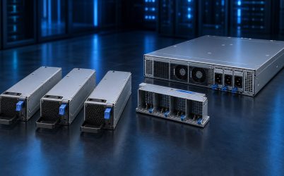
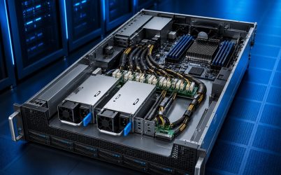
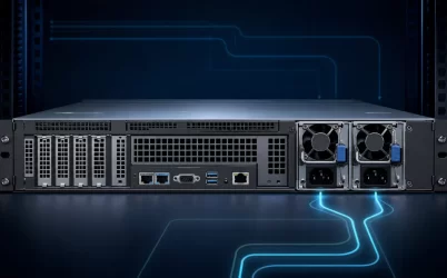
An 1100W dual hot-plug redundant server power supply usually describes two 1100 W-class modules installed in a server as a 1+1 pair. In that redundant mode, the server is generally limited to the usable output of one module—not 2200 W—because either unit must carry the permitted load after its partner is removed or fails. “Hot-plug” means a supported module can be replaced while the server remains powered through the healthy path. Those statements apply only when the exact modules, host power distribution board (PDB), input source, airflow, firmware, and service procedure support that operating mode.
The phrase describes three boundaries at once
The 1100 W figure is a module output rating under conditions defined by its manufacturer. It is not a prediction of server consumption and may not be available at every input voltage or environmental condition. “Dual redundant” describes an installed topology, commonly 1+1, in which either supported path can supply the approved server load. “Hot-plug” describes a controlled service event: one module is disconnected and withdrawn without intentionally shutting down the host.
Search results for this phrase are dominated by server configurators, product guides, replacement parts, and procurement descriptions. That makes the query partly a compatibility lookup. A buyer may be specifying a new server option, replacing a failed module, or checking whether an 1100 W pair suits a planned configuration. The wattage class can narrow the search, but it does not identify a safe replacement. Exact host support and module identity remain decisive.
| Claim | What it establishes | What it does not establish |
|---|---|---|
| 1100 W class | A nominal module capacity under documented conditions | Available output at every input, temperature, or airflow |
| Dual redundant | Two paths can participate in a supported fault-tolerant mode | 2200 W of fault-tolerant load or independent upstream feeds |
| Hot-plug | Live removal and insertion are designed into the system | Safe interchangeability among look-alike modules |
Read the pair through four operating states
The clearest way to understand an 1100 W dual pair is to follow the server through normal operation, loss of one path, live replacement, and restoration. Each state asks a different question; passing only the normal state does not demonstrate redundancy.
State 1: both modules are healthy
Many platforms operate both modules and share current, although supported policies can differ. The load seen by each module affects conversion loss, fan behavior, and reported telemetry. Equal sharing is an architectural goal, not a universal promise of perfectly equal readings. Input voltage, component tolerance, firmware policy, and measurement accuracy can create a difference. The host documentation should define acceptable behavior and whether mixed models or revisions are allowed.
State 2: one module or feed disappears
The healthy path must assume the server load without the shared DC bus leaving its acceptable operating envelope. The important quantity is the survivor’s usable capacity under the deployed mains voltage, inlet temperature, altitude, airflow, and transient demand. If that capacity is 1100 W only under a particular input condition, the redundant server limit must honor that condition. Adding two faceplate ratings would describe an aggregate 2+0 mode, not the protected 1+1 state.
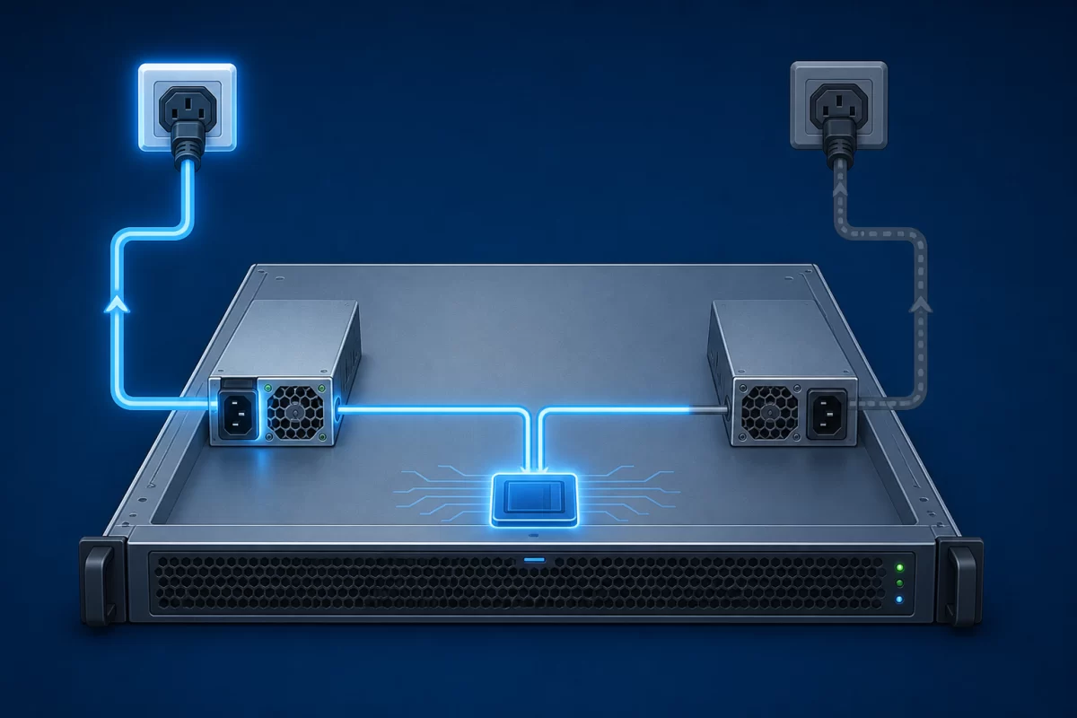
State 3: the failed unit is removed and replaced
During withdrawal, connector contacts separate in a designed sequence and the remaining path stays isolated from the service action. During insertion, inrush must be controlled so the new module does not pull the shared bus down. The server-side connector, PDB, ORing or equivalent isolation, control signals, firmware, and mechanical guides all participate. A handle alone does not create hot-plug capability.
State 4: the pair returns to normal
The inserted module must be recognized, start correctly, synchronize with the power system, and enter the supported sharing or standby policy. Alarms should clear only when the path is genuinely available. This restoration stage matters operationally: a server that stays online during replacement but never returns to a protected state remains exposed to the next fault.
What workload territory an 1100 W class can cover
An 1100 W module class often appears in enterprise rack servers whose processor, memory, storage, networking, fan, and moderate accelerator populations sit above lower-power options but below the envelopes that drive larger modules. That observation is a market pattern, not a configuration guarantee. Two servers with the same processors can differ materially because of memory population, PCIe devices, drive count, fan policy, firmware power limits, and workload behavior.
For a hypothetical sizing exercise, suppose measured or platform-calculated demand reaches 760 W during a representative workload and short events raise the required source response above that steady level. The engineering question is not whether 760 is below 1100. It is whether one approved module can support the continuous and dynamic demand after input and environmental derating, while the PDB, connectors, and cooling remain within their own limits. The example illustrates the method; it is not evidence that an arbitrary 760 W server belongs on an arbitrary 1100 W PSU.
CPU-heavy virtualization, storage-rich systems, and some general-purpose GPU configurations may fit this class. Dense accelerator servers can exceed it or impose transient and connector-distribution constraints before the average load reaches the label. Conversely, a lightly configured server may function on 1100 W modules but operate each unit at a load point that is not ideal for cost or efficiency. A platform configurator or vendor power-planning tool is the appropriate starting point for a named server.
The live replacement interval is the hardest part of the promise
A running server changes electrical and thermal state the moment one module leaves. The surviving unit carries more current, may increase fan speed, and may report a degraded redundancy alarm. Removing the wrong module, disturbing both cords, blocking exhaust, or inserting an unsupported spare can turn a recoverable event into an outage.
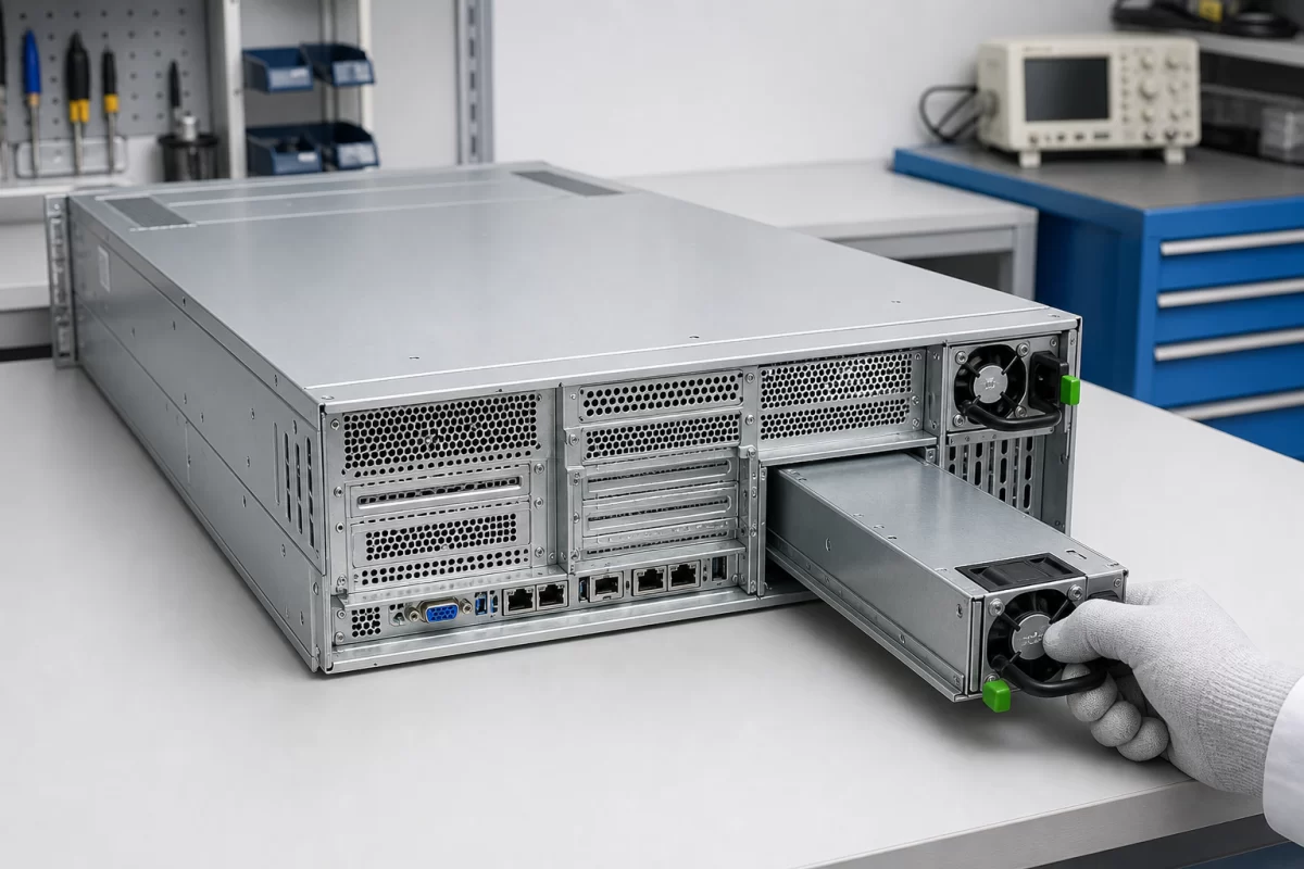
The service procedure should identify the failed bay from system indicators and management data, then trace its cord before touching hardware. The replacement needs the approved identity, connector and keying, airflow direction, firmware relationship, and electrical behavior—not merely the same 1100 W marking. After insertion, the operator should confirm that the system sees both paths and that redundancy has returned. These are host-specific actions, so the server manual takes precedence over a generic removal sequence.
The dedicated redundant hot-swap power supply article examines connector sequencing, inrush, isolation, and service rules in greater depth. For this wattage class, the practical consequence is that the entire 1100 W permitted load may sit on one path throughout the replacement interval.
Two modules do not automatically create two failure domains
If both cords terminate on the same rack PDU, branch circuit, or upstream source, the server may tolerate a PSU-module failure yet still stop after that shared source fails. Connecting the modules to separate A and B rack feeds can extend the protected path, provided the PDB and server topology preserve continuity. Feed independence is therefore separate from module redundancy.
Common-cause risks also remain inside the chassis. A shared PDB, busbar, downstream converter, cooling dependency, firmware defect, or connector fault can affect both modules. Redundancy is best stated as a tolerated event rather than a general reliability adjective: for example, continued operation after one supported PSU module is removed while the server remains below the documented single-module limit. The broader power supply redundancy architecture explains how module count and failure domains relate.
Input conditions can move the 1100 W boundary
Some 1100 W-class products support broad AC input; others are intended for a narrower source or make different output available at low-line and high-line input. Connector and cord requirements can also vary by platform. No generic article can assign an input range, current draw, efficiency tier, or branch-circuit requirement to every module carrying this wattage description.
Facility planning starts with the exact input table and efficiency data for the selected module. AC input power is greater than delivered DC output because conversion is not lossless, and the branch circuit may serve multiple devices. During a single-module state, the surviving supply’s input current and heat loss change with its operating point. Rack PDU capacity, cord rating, connector type, phase balance, and source-failure policy must be evaluated using supported data rather than by dividing 1100 W by a convenient nominal voltage.
Why an 1100 W label cannot identify a spare
Server PSUs that share a wattage can differ in envelope, depth, blind-mate connector position, pin assignment, standby output, control sequencing, PMBus implementation, airflow direction, efficiency, input support, firmware identity, and approved mixing behavior. Even units marketed for the same server family may depend on generation, chassis, PDB, or configuration.
A reliable spare record contains the server model and revision, installed PSU part numbers, supported alternates, firmware requirements, PDB identity, input type, airflow direction, and any rule requiring identical pairs. The server PSU wattage reference shows how rating, usable output, server demand, and facility input should be kept separate. That separation prevents a capacity number from being mistaken for a compatibility key.
Where the 1100 W pair earns its place
This class is useful when one supported 1100 W module can sustain the server’s approved continuous and transient envelope under the real input and cooling conditions, while two installed paths provide the required service continuity. It occupies a practical middle ground for many rack-server configurations: more headroom than lower-power options without automatically moving to the electrical, thermal, and cost implications of a larger supply.
The pair’s value appears during the abnormal minutes, not in the sum printed on two labels. One module carries the machine, the failed path stays isolated, the replacement enters without collapsing the bus, and the system returns to a protected state. If the exact host documentation supports those four moments at the intended load, “1100W dual hot-plug redundant” describes a meaningful system capability rather than three disconnected catalog terms.