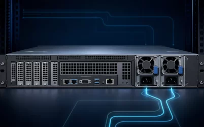
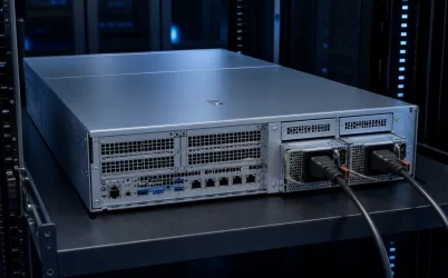
A 1600W dual hot-plug redundant server power supply normally means two 1600 W-class modules operating as a 1+1 pair. The protected server load is therefore governed by one module’s usable output, not by adding the two labels to claim 3200 W of redundant capacity. This class is often chosen for dense dual-socket, accelerator, storage, or heavily expanded 2U systems, but the full 1600 W may depend on high-line input and model-specific thermal conditions. A correct design joins four boundaries: the server configuration, single-module capacity, high-current PDB path, and rack power source.
At 1600W, the facility becomes part of the server specification
Lower-power server options can sometimes be treated mainly as chassis components. A 1600 W module makes that separation harder. The input table for the exact PSU may provide different output limits at different mains voltages, while its cord, inlet, rack PDU, and branch circuit must carry the corresponding input current. One documented 1600 W server PSU, for example, makes its full rating available only on a high-line AC range; that is evidence for that product, not a category-wide rule. Other models can have different ranges and derating behavior.
This changes procurement. A server configuration that is valid in a 200–240 V rack may enter a lower supported power state when moved to a low-line lab, staging room, or branch office. The machine may refuse a configuration, apply power caps, report a redundancy warning, or simply have less surviving capacity, depending on the platform. The relevant question is not whether the plug fits. It is whether one installed module has its required output rating on the actual source.
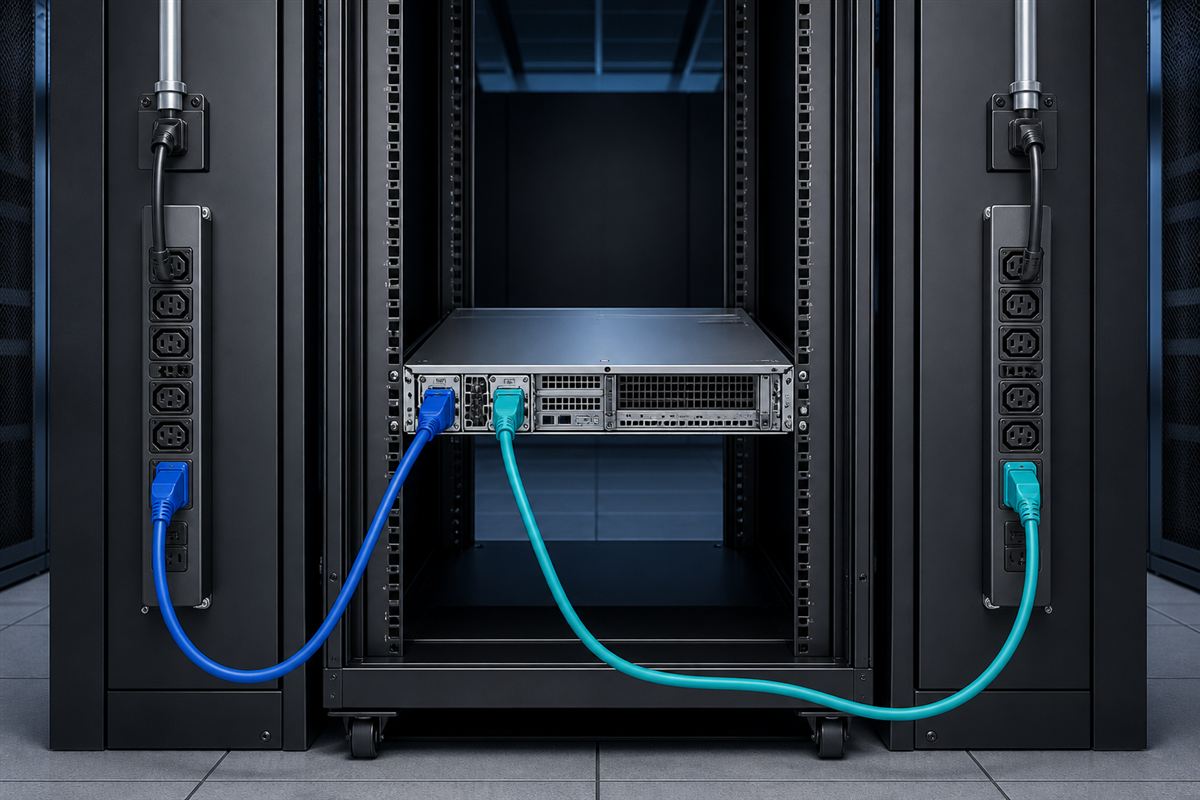
A and B feeds add another layer. Two cords connected to one rack PDU protect against a module fault but not against loss of that PDU. Separate feeds can extend the failure boundary upstream, provided each feed is independently capable of supporting the server in the one-module state. Source independence, branch loading, connector selection, and rack PDU capacity should appear in the deployment record alongside the PSU part number.
The 1600W class serves configuration density, not a generic server size
This power class appears where a platform needs more room than mainstream CPU-and-storage configurations, yet still uses chassis-integrated hot-plug modules rather than an external power shelf. Candidate loads include high-core-count processors, large memory populations, multiple PCIe devices, dense NVMe or rotating storage, high-performance network adapters, and supported accelerator options. A particular configuration can include several of these loads, but no component list alone proves that 1600 W is sufficient.
Platform demand is shaped by firmware power limits, fan policy, drive start behavior, voltage-regulator losses, standby loads, and short transitions. Accelerator and processor boosts may overlap. Fans may accelerate after one PSU is removed because the thermal path or redundancy policy changed. Storage loads can rise together during spin-up or recovery. The supply sees the combined DC-bus behavior, while individual PDB branches and connectors see concentrated portions of it.
| Configuration pressure | Why 1600W may be considered | Boundary that can still dominate |
|---|---|---|
| High CPU and memory population | More sustained platform demand and cooling load | Single-module output at the deployed input and inlet temperature |
| Supported accelerator expansion | Higher steady load and faster load transitions | PDB branch, connector distribution, and transient behavior |
| Dense storage | Drive population and simultaneous operating events | Harness allocation, spin-up policy, and fan demand |
| Many high-speed adapters | Added PCIe and cooling consumption | Slot power allocation and approved chassis configuration |
The table describes design pressures rather than supported combinations. A server vendor’s configuration tool or technical guide is the authoritative source for a named platform. For a custom chassis, the load model must be reconciled with the exact PSU, PDB, harness, airflow, and control implementation.
One module must own the abnormal operating interval
In normal 1+1 operation, both modules commonly contribute current. If the server consumes 1,000 W at the DC bus, approximately balanced modules may each operate near half that load. The redundancy event changes the operating point immediately: after one path is lost, the survivor supplies essentially the full bus demand. That transfer—not the comfortable shared state—is where the 1600 W selection earns its meaning.
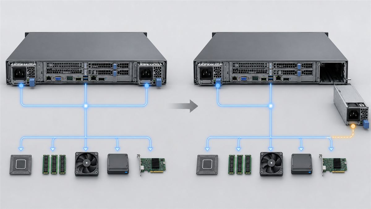
A useful capacity argument begins with the highest supported server demand during the degraded interval. It then applies the selected module’s published limits for input voltage, temperature, altitude, and airflow. Dynamic demand must remain within the response expected by the host platform, and downstream conductors must carry the resulting current. This is not a request to add an arbitrary percentage to a nameplate. It is a comparison between a defined server operating envelope and documented component envelopes.
At a nominal 12 V output bus, 1600 W corresponds arithmetically to about 133 A. That calculation illustrates why contact resistance, copper distribution, and current allocation matter; it does not assert that every 1600 W module uses 12 V, exposes 133 A through any single contact, or defines its rating in the same way. Modern platforms may use different bus voltages or architectures. The exact output and interface data control the design.
Hot-plug transfer is a high-energy electrical event
“Hot-plug” means a supported module can be removed and inserted while the host remains energized through another valid path. The removable handle is only the visible part. On withdrawal, the departing module must stop driving the shared bus without backfeeding or pulling it down. Isolation elements on the PSU or PDB prevent one faulted path from disabling the healthy path. Connector sequencing separates power and control contacts in an intended order.
Insertion creates the opposite challenge. Input capacitors and internal stages initially look like a changing load to the source. Inrush control, standby power, presence detection, output enable, and current-sharing behavior must bring the replacement online without upsetting the operating server. After startup, the pair should settle into its supported sharing or standby policy and restore the platform’s redundancy indication.
The service interval can also be thermally significant. One module carries more electrical load, and an empty bay can alter pressure or create an airflow bypass. Operators should identify the failed path from platform indicators, trace its input cord, follow the server’s removal sequence, install an approved replacement, and confirm that the redundant state actually returns. Powernexu’s hot-swap power architecture article covers sequencing and isolation in more detail.
The PDB has to distribute a concentrated power envelope
A 1600 W module does not normally feed every load directly. Its blind-mate output reaches a PDB or backplane that combines the redundant paths, carries isolation and sensing functions, and divides current among motherboard, accelerator, storage, and auxiliary branches. The module rating cannot raise a PDB trace, busbar, connector, cable, or protective device above its own supported limit.
Distribution matters especially in accelerator configurations. Total server demand may sit below one-module capacity while one connector group or harness approaches its boundary. Replacing the harness with an adapter does not create more copper capacity or correct an unsupported pin assignment. Remote-sense routing, standby rails, power-good behavior, enable logic, and management signals can also be platform-specific. A mechanically similar PSU is not necessarily electrically interchangeable.
The CRPS PDB assembly guide explains this boundary at component level. For the 1600 W use case, its practical lesson is direct: capacity must reach the loads through an approved distribution topology, not merely exist at the module output.
Telemetry helps distinguish reserve from an approaching boundary
Supported server platforms may expose PSU input power, output power, temperature, fan state, status, or inventory through the BMC. These readings are useful for observing the difference between ordinary sharing and a one-module event. They can reveal persistent imbalance, show whether a replacement is recognized, and help operators understand how close an actual workload comes to the platform’s policy limits.
Telemetry is not automatically a precision instrument or a substitute for the configuration rules. Update rate, accuracy, supported commands, and alarm interpretation depend on the module and host. A dashboard average can also conceal a brief demand transition. Use management data in the role the vendor documents, and preserve external facility measurements where rack or branch planning needs them.
Inventory data is equally valuable. A 1600 W spare should be selected by supported part identity, server generation, PDB and connector family, input requirements, airflow direction, firmware policy, and approved pair-mixing rules. Equal wattage and a similar front face are weak compatibility evidence.
Why 1600W is different from the neighboring wattage classes
The recently discussed 1100W dual hot-plug redundant class often occupies a middle enterprise-server range, while the 750W redundant class naturally suits more bounded compute, storage, network, and edge configurations. Moving to 1600 W is not simply purchasing an additional block of capacity. It can move the server into a different input-voltage expectation, cord and rack-PDU plan, thermal density, PDB current scale, and supported configuration tier.
Conversely, selecting 1600 W for a lightly loaded machine is not automatically harmful, but it may add cost, constrain compatible options, or place two modules at a low normal operating point. The server vendor may offer several PSU tiers precisely so the configured workload, growth plan, and facility environment can be matched rather than maximized indiscriminately.
The protected operating envelope is the real deliverable
A defensible 1600 W redundant deployment can be described without marketing shorthand: the named server configuration remains within one approved module’s usable output on either rack feed, the PDB delivers that power to every branch, the cooling system supports the one-module interval, and a failed unit can be replaced without disrupting the DC bus. The full rating is available under the intended mains and environmental conditions, and the platform returns to a protected state after service.
That description exposes the value of this power class. It supports dense chassis configurations while retaining module-level service continuity, but only where the rack source and internal distribution are designed for the same envelope. In a 1600 W system, the server bay, PDB, cord, rack PDU, and facility feed are not separate purchasing details; together they define whether the redundancy promise exists.