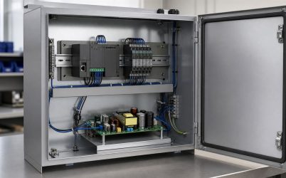
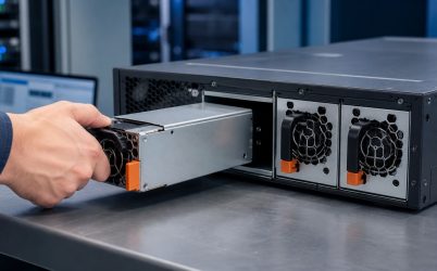
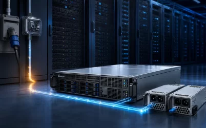
A 2000W dual hot-plug redundant server power supply is best understood as a high-density power architecture, not a promise that two modules provide 4000W to the workload. In a protected 1+1 arrangement, each 2000W-class module is expected to support the defined server load during the interval when its partner, its input feed, or its power path is unavailable. That makes this class relevant to dense GPU, accelerator, storage, and HPC configurations whose sustained demand and short load excursions no longer fit comfortably inside lower-power envelopes. The decisive questions are therefore where the single-module boundary applies, how the facility supplies it, and whether the shared DC path can carry it.
The 2000W class changes the unit of analysis
At modest power levels, a PSU discussion can remain mostly inside the chassis. Near a 2000W module rating, the useful unit becomes the complete route from branch circuit to silicon. Input source, cord, inlet, hot-plug contacts, power distribution board (PDB), bus conductors, connectors, cooling path, and workload controls all participate in the usable envelope.
The number itself should be treated as a class or design boundary unless an exact manufacturer’s datasheet establishes its conditions. A real module may have input-dependent output limits, environmental derating, defined cooling requirements, and model-specific interfaces. The title does not establish any of those details. It describes the system problem: preserving a large server load through a single power-path loss while retaining live serviceability.
This separates the topic from a general server PSU wattage exercise. The central issue is not merely estimating a peak. It is arranging a power domain so that an abnormal state remains inside a known, supportable boundary.
A capacity map should have three layers
A useful 2000W-class design starts with three different boundaries that are often compressed into one number.
| Boundary | What it represents | Why it can become limiting |
|---|---|---|
| Module envelope | Output available from one PSU under stated conditions | Input range, temperature, airflow, or model-specific derating |
| Distribution envelope | Power the PDB, bus, contacts, and load connectors can deliver | Concentrated current, contact heating, trace or cable limits |
| Protected workload envelope | Load the server may sustain after one module or feed is lost | Transient demand, cooling response, and recovery behavior |
The protected workload should sit within the intersection of all three, not merely below a nameplate. A configuration can pass a static power estimate yet fail this map if a concentrated accelerator branch exceeds its connector path, if loss of one module changes airflow, or if the remaining PSU reaches a protection threshold during a simultaneous compute excursion.
For this reason, the workload model should preserve time. Idle, ordinary production, sustained computational phases, and brief transitions are electrically different. Averaging them together conceals the interval most likely to challenge the surviving module.
The single-module interval is the architectural center
In normal operation, two healthy modules may share current and each can operate well below its individual ceiling. That balanced state is useful for loss reduction and thermal distribution, but it is not the state that proves redundancy. The defining interval begins when one path stops contributing.
The surviving module must accept the transferred share quickly enough that the common bus remains within the server’s permitted range. Isolation must prevent a failed module from dragging down that bus. Control logic should recognize the state, report it, and avoid oscillating between paths. If replacement is initiated, the insertion sequence must limit disturbances as the new module’s input capacitors charge, auxiliary functions start, output synchronizes, and current sharing resumes.
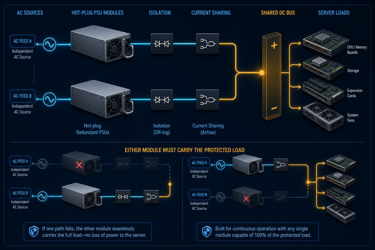
That event sequence explains why two supplies connected to one board are not automatically a redundant hot-plug system. The behavior depends on coordinated modules, mating interface, PDB, control signals, firmware, and service procedure. The dedicated explanation of hot-swap server power supplies covers the live insertion mechanism; in a 2000W-class system, its consequences are magnified by the energy moving through the shared path.
High-density loads make locality matter
A server’s total input does not reveal where current travels after conversion. CPU sockets, accelerator groups, memory, storage, fans, and motherboard regulators can occupy different downstream branches. A 2000W-class architecture may therefore be constrained by a local path even while aggregate output appears acceptable.
Accelerators are particularly relevant because power can change rapidly with workload state. Platform management may smooth, cap, or coordinate demand, but those functions are part of the server design rather than properties implied by the PSU wattage. A procurement specification should distinguish the allowed sustained configuration from the short-duration response the power system must tolerate.
Distribution geometry also influences loss and temperature. Higher current through a contact or conductor creates greater resistive heating; uneven sharing can concentrate that stress in one module bay or bus segment. Designers should examine current-share accuracy across the intended operating range and the physical symmetry of the two paths. The question is not whether both modules report “healthy,” but whether their shared operating point keeps each path inside its electrical and thermal limits.
Input power has to survive the same fault story
Dual modules provide limited resilience if both cords terminate on the same upstream failure domain. Where the availability objective requires feed independence, module A and module B should trace to appropriately separated sources, protection devices, rack PDUs, and upstream infrastructure. The exact topology depends on the facility, but the fault boundary must be explicit.
Input voltage also affects what the label means. Some high-power supplies do not make their maximum output available under every nominal input condition. Never infer a universal low-line or high-line capability from the 2000W phrase. Obtain the output-versus-input data for the precise part and use it to define the permitted installation.
Facility planning needs input demand rather than output rating alone. Conversion loss, power factor behavior, cord and connector ratings, protective-device coordination, and simultaneous rack loading influence the branch design. Multiplying the headline wattage by the server count is not a complete rack calculation, yet ignoring the surviving-module state is equally misleading: after a feed loss, the remaining branch may inherit more load from every affected server at once.
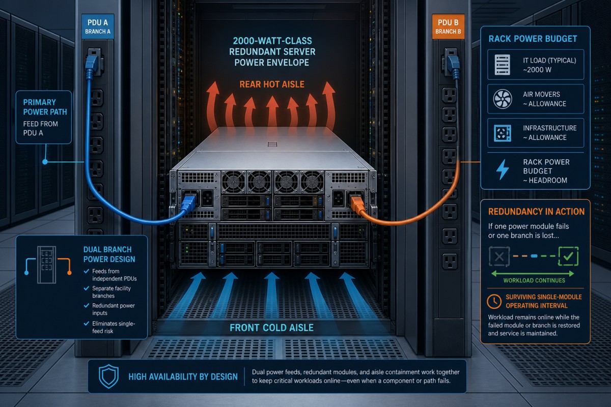
This creates a useful distinction between server redundancy and rack resilience. A server may ride through one PSU removal while a rack remains vulnerable to a shared upstream device. Conversely, two facility feeds do not protect a server whose internal PDB contains an unaddressed common failure point.
Cooling reserve becomes dynamic after a module loss
Electrical capacity and thermal capacity move together. During balanced operation, loss is divided between modules and both internal fans may contribute to the rear airflow pattern. After one PSU is removed, the survivor converts the entire protected load while the empty bay can alter pressure and recirculation unless the chassis design controls it.
A 2000W-class selection therefore needs a thermal statement tied to orientation, inlet temperature, altitude where relevant, fan control, airflow impedance, and the module-loss condition. These are not generic values that can be supplied from the keyword. They belong to the exact chassis and module documentation.
Temperature telemetry is useful when it shows the approach to a real boundary rather than merely presenting a dashboard. Correlating module output, fan response, inlet conditions, and component temperatures during representative workloads can reveal whether apparent electrical headroom is being purchased with excessive acoustic noise, rapid fan operation, or reduced environmental margin.
Telemetry should describe transitions, not just steady state
At this power density, management data earns its value by explaining change. The BMC may need to identify input loss, module removal, output fault, degraded redundancy, current imbalance, or thermal limiting. Exact PMBus commands and sensors are model-specific, so support must be confirmed rather than assumed from a modular form factor.
Sampling and alarm design should reflect the event being observed. A slow trend is appropriate for rising inlet temperature; it may miss a short transfer disturbance. A latched fault can preserve evidence that disappears once a replacement module is inserted. Operational software should also distinguish “both modules present” from “redundancy available,” because a present module can be unpowered, incompatible, faulted, or unable to support the required envelope at the available input.
This data can support workload policy. If redundancy is lost, a platform may alert operators, cap accelerators, postpone a batch job, or migrate work according to the service objective. Such responses are system choices; the PSU alone does not guarantee them.
Where a 2000W-class pair is a rational fit
The class is most credible where a dense configuration genuinely needs its protected capacity: multi-accelerator compute, high-core-count HPC, storage with substantial device and fan demand, or consolidated servers whose expansion envelope would press lower-power modules too close to their abnormal-state boundary. It can also reduce the need to split one server across a more complex set of lower-rated power modules, provided the facility and chassis support the resulting concentration.
It is less compelling when the ordinary and worst permitted workloads fit comfortably into a smaller protected envelope. Oversizing can move normal operation to a less favorable point on the module’s actual efficiency curve, consume scarce facility capacity, or impose a form factor and airflow strategy the chassis does not need. Those outcomes cannot be judged from a generic efficiency badge; the exact module curve and operating distribution are required.
The right purchasing language is therefore conditional: state the protected workload profile, permitted input sources, module-loss behavior, downstream distribution, environmental envelope, mechanical interface, service access, and management behavior. If replacement interoperability matters, identify the approved part or platform compatibility rather than requesting an unspecified “2000W hot-plug PSU.” A wattage match does not establish connector, signaling, airflow, firmware, or current-share compatibility.
The real advantage is concentrated continuity
A 2000W dual hot-plug redundant server power supply earns its place when the server must keep a dense workload online through loss and replacement of one power path. Its advantage is not simply a larger number; it is the ability to concentrate substantial protected capacity into a serviceable architecture. That advantage remains real only when the single-module interval is supported end to end—from independent input and fault isolation through the PDB and cooling path to workload behavior. Define that interval first, and the 2000W class becomes an engineering envelope rather than a marketing label.