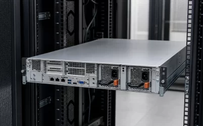
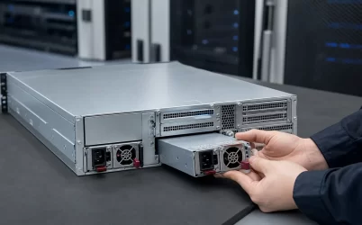
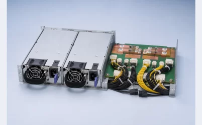
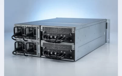
A 4U fully modular redundant server power supply is not one universally standardized product. The phrase usually describes a 4U server power assembly that combines removable power modules, a redundant cage or power distribution board (PDB), and detachable output cables. Those three meanings of “modular” are often compressed into one marketplace title. Before ordering, separate the assembly into its physical parts and identify which cables, connectors, and distribution hardware are actually included. A 4U chassis provides room for the system, but it does not by itself establish PSU fit, motherboard compatibility, redundant capacity, or cable interchangeability.
Four words describe three different boundaries
The wording sounds specific, yet each term can refer to a different layer. “4U” normally describes a chassis about four rack units high, not the height or shape of the power module. “Redundant” describes an operating topology in which the intended load remains powered after a defined failure. “Modular” may describe removable AC-DC converter modules, detachable low-voltage cables, or a server platform assembled from replaceable subsystems. “Fully modular” is especially ambiguous because it is familiar from desktop ATX supplies, where every DC harness can be unplugged from the PSU body.
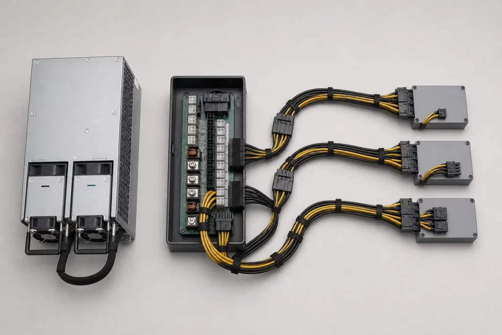
A redundant server assembly commonly has a different boundary. Two removable converter modules plug into a cage or PDB. The PDB combines and isolates their outputs, then presents fixed or detachable harness connections to the motherboard, processors, drives, fans, and accelerators. In that architecture, the hot-plug modules can be modular even when the downstream harness is permanently attached. Conversely, a supply can have fully detachable cables without offering any redundancy at all. Chassis fit and module behavior must therefore be resolved independently.
That distinction changes the purchasing question. Do not ask only whether the listing is “fully modular.” Ask which interfaces can be disconnected, which components can be replaced independently, and which parts form a qualified set.
The useful product is an assembly, not a pair of metal boxes
Two power modules sitting beside each other do not automatically create a redundant output. The cage, PDB, connector sequencing, output isolation, current-sharing behavior, control signals, and chassis wiring make the pair operate as a system. A complete commercial bundle may include all of those elements, or the offer may contain only two replacement modules for an existing host.
The scope can be divided into five physical layers:
- Input layer: inlet type, line cords, permissible AC or DC range, and the intended A/B feed arrangement.
- Converter layer: the removable PSU modules, their output rating under stated input conditions, and their cooling direction.
- Combining layer: cage, PDB, ORing or equivalent isolation, current sharing, standby output, and management interface.
- Harness layer: detachable or fixed cables, conductor gauge, connector families, pin assignments, branch quantities, and length.
- Load layer: motherboard, CPU power inputs, storage backplane, accelerator boards, fans, and auxiliary devices.
If a quotation names only the converter rating, most of the usable configuration remains undefined. A photograph can show the rear cage and cable count, but it cannot prove pinout, conductor rating, firmware support, or whether the photographed accessories ship with the quoted part number.
Detachable cables transfer responsibility to the cable map
A detachable harness improves assembly flexibility only when the cable identity is controlled. The PSU-side socket is not a universal interface. Two cables can physically fit similar housings while assigning voltage, return, sense, or control contacts differently. A cable from another supply family should therefore not be treated as interchangeable unless the manufacturer explicitly identifies that combination as supported.
For a 4U server, begin with the load endpoints rather than a generic connector count. Record the motherboard main-power interface, the number and type of processor feeds, storage-backplane inputs, GPU or accelerator inputs, and any fan or auxiliary branches. Then map each endpoint back through the harness to the PDB. The map should preserve connector keying, pin assignment, cable length, conductor size, branch sharing, and the routing path through the chassis.
Length is an electrical and mechanical variable. A harness that reaches only under tension can load a connector or obstruct service. Excess length can block fan inlets, cross sharp sheet-metal edges, or occupy the extraction path of a drive cage. High-current branches also develop voltage drop and heat according to current, conductor resistance, contact resistance, and the number of connections. A “more connectors” bundle is not necessarily a better bundle if several high-load sockets share a branch that was not designed for their combined current.
Modularity also changes spare planning. Keeping a spare converter does not restore the system if a proprietary PDB-to-load cable is damaged and no matching harness is available. A maintainable bill of materials gives each replaceable cable an identity rather than describing the whole set as “included modular cables.”
Four rack units create routing freedom—and competing claims on it
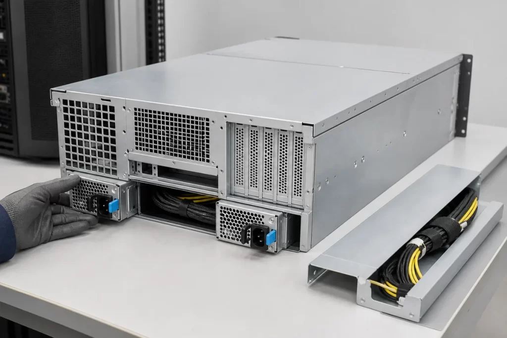
A 4U enclosure offers more vertical space than a 1U or 2U server, but that space is already contested by full-height cards, GPU support structures, storage bays, fan walls, radiators, and rear I/O. The redundant power cage may occupy an ATX-like rear opening, a dedicated side bay, or a proprietary region. Chassis height does not guarantee that any nominal “4U redundant PSU” will align with the mounting aperture.
Measure the complete cage envelope, mounting-hole pattern, insertion direction, latch clearance, and rear extraction distance. Also check the internal keep-out zone behind the PDB. A connector or cable bend that fits while the cover is removed may collide with the cover, expansion card, or fan duct after final assembly. Rear rack clearance matters because a module must pass the cabinet door, vertical PDU, and cord-management hardware during service.
Airflow belongs in the same layout drawing. Converter modules may move air front-to-rear or rear-to-front, or depend partly on the chassis pressure field. Detachable harnesses should not form a curtain across module inlets or the central fan wall. The system designer needs the supported airflow direction and operating envelope for the exact module; the visual presence of a fan is not evidence that any installation orientation is acceptable.
Redundant capacity follows the surviving configuration
Redundant labels are sometimes interpreted as permission to add the nameplate ratings of two modules. In a 1+1 arrangement, however, the system is generally expected to carry the required load after either module is unavailable. The relevant capacity boundary is therefore the supported output of one surviving path under the actual input voltage, inlet temperature, airflow, and platform limits—not simply twice the number printed on one module.
Consider a hypothetical server with a measured or modeled 1,050 W sustained maximum and a 1,320 W short-duration demand at a defined workload transition. If each candidate module is advertised at 1,600 W, the comparison is not finished. The exact documentation must show that the candidate can provide the required output at the site’s input range and thermal condition, while the PDB, harness branches, connectors, and load controls can carry the transition. A high-line-only full rating would change the result at a low-line site. A host-enforced power cap could also be lower than the converter’s label.
Configurations with three or four modules introduce other interpretations, such as N+1, 2+2, or capacity sharing without the same failure guarantee. State the failure that the architecture must survive and calculate the available output after that event. The word “redundant” is incomplete until the failure boundary and surviving capacity are named.
Service modularity is different from hot-swap capability
A component is modular when it can be replaced as a defined unit. Hot swap adds a stronger claim: removal or insertion is supported while the remaining system continues operating under specified conditions. Detachable internal DC cables are normally service connections, not live-service interfaces. Power should be removed and the documented discharge and service procedure followed before changing them unless the host manufacturer explicitly provides another method.
Hot-plug PSU modules rely on more than handles and latches. The connector and control sequence must manage protective earth where applicable, precharge or inrush behavior, output isolation, presence detection, and load transfer. The surviving path needs enough capacity, and both modules should belong to a supported pairing policy. A mechanically removable module from the same family may still differ in firmware, airflow, input class, or host support.
The cleanest service boundary leaves fixed chassis cabling undisturbed when a converter module fails. If replacing one PSU requires opening the chassis and unplugging every load cable, the system may be fully modular in a marketing sense but inefficient to repair in a rack. Conversely, a fixed, documented PDB harness can make module replacement fast and repeatable. The most valuable form of modularity depends on the failure expected to be serviced.
Translate the marketplace phrase into a bill of materials
A useful request for quotation should replace the compressed product phrase with named components. Specify the intended chassis or provide its mechanical drawings; identify the motherboard and powered devices; state the required redundancy mode and failed-state load; and define site input, airflow, and management needs. Ask the supplier to identify the exact module pair, cage or frame, PDB, every output harness, line cords, mounting hardware, and any control cable included.
The output-cable schedule should connect each supplied cable part number to its source socket and load endpoint. If drawings or pinout documents are controlled by the manufacturer, obtain the applicable revision rather than reconstructing the interface from photographs. For an unfamiliar platform, a sample assembly can resolve spatial routing and connector access before volume procurement, but it does not substitute for supported electrical documentation.
Commercial comparison becomes clearer once quotations share the same boundary. One offer may look expensive because it contains the complete redundant cage and harness set; another may be only a pair of modules that assumes an existing PDB. Separating those scopes prevents a low headline price from becoming an unusable shipment.
A fully modular design should reduce rack-side work
The strongest 4U power architecture is not the one with the greatest number of unplugged cables. It is the one whose replaceable boundaries match real service events. Converter modules should be removable without disturbing unrelated loads, while harnesses that need configuration flexibility should have controlled identities, adequate routing, and supported pin assignments. The cage and PDB should remain explicit parts of the system rather than invisible accessories.
Read “4U fully modular redundant server power supply” as a starting description, then resolve it into chassis geometry, converter modules, combining hardware, cable map, load endpoints, and a stated redundancy mode. Once those relationships are defined, modularity becomes an engineering advantage. Until then, it is only an adjective attached to an incomplete bundle.