A 4U modular redundant server power supply is best understood as a multi-module power architecture, not merely a replaceable PSU fitted into a tall chassis. Four rack units can accommodate high-power CPUs, GPUs, storage, and several power modules, so the central design question is how many modules the workload needs and how many may be lost without interrupting service. A 1+1, 2+1, and 2+2 arrangement can all be called redundant, yet they provide different usable capacity and protect against different feed failures. The correct topology must be defined from the degraded operating state before module wattage or efficiency is compared.
Module count is not the redundancy topology
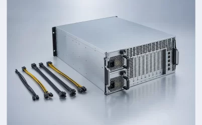
A chassis with four installed PSUs does not automatically provide two-module fault tolerance. The notation should describe the number required to carry the intended load and the number reserved by the operating policy. In a simplified 2+1 topology, two modules provide the necessary capacity and one additional module allows one module failure. In 2+2, two modules provide capacity while two more can preserve that capacity after a defined pair is lost. Other platforms may implement load sharing, cold redundancy, or input grouping differently, so the host documentation remains authoritative.
This distinction matters because a physical bay count can support several policies. The same four bays might operate as 3+1 for greater normal capacity, 2+2 for a stronger paired failure boundary, 2+1 with an empty bay, or 4+0 with no capacity reserve. Firmware power caps, installed module identity, and input-feed assignment can determine which mode is actually available.
An HPE 4U server hardware guide provides a platform-specific example of PSUs supporting 2+1 or 2+2 redundancy. That does not make those modes universal, but it demonstrates why a four-module 4U system needs an explicit topology rather than the generic label “redundant.”
Start with the 4U load map, then assign modules
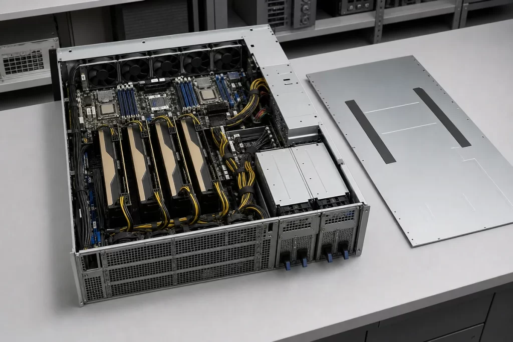
Four-unit servers vary widely. One may be a conventional dual-socket compute server with many drives; another may hold four or eight accelerators; a storage chassis may concentrate load in disks and fans during spin-up or rebuild; a multi-node platform may divide the enclosure among several independently managed compute nodes. A single total-watt estimate hides the timing and location of those loads.
Build the load map around operating states. Include boot, accelerator initialization, maximum supported compute, storage rebuild, fan escalation, and any power-capped degraded mode. Record which load zones are essential after a PSU or feed failure. A server may continue useful work at a reduced GPU limit even when it cannot sustain its unrestricted peak. If that behavior is intentional and documented, the redundancy requirement can be expressed as a surviving service level rather than a vague demand for “full power.”
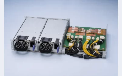
Location also matters. The power distribution assembly may divide output among motherboard, accelerator, storage, and fan zones. A module group with sufficient aggregate capacity does not help if one branch, connector, or distribution plane cannot carry the rearranged load. The topology drawing should therefore connect modules to actual load zones instead of ending at a single box labeled server.
Surviving capacity changes with every allowed failure
A useful capacity calculation enumerates module states. Let each module have a supported output of P under the actual input voltage and thermal condition. If two modules are required, the nominal capacity boundary is 2P; adding modules changes the failure reserve, not automatically the load entitlement. Platform, PDB, connector, or firmware limits can impose a lower ceiling.
Consider a hypothetical four-bay server using modules that each support 2,000 W at the deployment condition. The following arithmetic illustrates topology, not a specification for a real product:
| Configured mode | Modules needed for load | Extra modules | Simplified surviving capacity after one module loss |
|---|---|---|---|
| 1+1 | 1 | 1 | 2,000 W |
| 2+1 | 2 | 1 | 4,000 W |
| 3+1 | 3 | 1 | 6,000 W |
| 2+2 | 2 | 2 | 4,000 W after a supported two-module group loss |
The last row requires the most care. A 2+2 label may protect a defined pair or feed group, but it does not mean any arbitrary two modules may fail under every implementation. The PDB topology, input grouping, control policy, and cooling state define the supported combinations. Likewise, a transient above the surviving continuous boundary may require host throttling even when it is brief.
A/B feeds turn module placement into infrastructure design
Module redundancy and feed redundancy are separate. Four healthy PSUs connected to one rack PDU remain vulnerable to that PDU, upstream breaker, cord bundle, or maintenance action. A 2+2 architecture often becomes valuable when two modules belong to feed A and two belong to feed B, allowing either feed group to carry the intended service level.
The physical bay assignment must match the electrical grouping recognized by the platform. Alternating modules across feeds may improve thermal symmetry, while adjacent grouping may match separate distribution planes; neither arrangement should be guessed. Cord labels, PDU outlets, breaker capacity, phase loading, and BMC reporting should preserve the intended association from the module inlet to the upstream source.
Maintenance domains belong on the same map. If both feed groups pass through one transfer switch, one branch panel, or one cord-management path, a shared intervention can still remove all modules. The useful boundary extends beyond the rear handles to the first genuinely independent upstream points.
Input voltage can redraw the topology. Some high-output modules deliver their full rating only over a specified high-line range. If feed A and feed B differ in voltage class, or if a site expects operation from an alternate source, calculate the surviving capacity at that source condition. Redundant feeds are not equivalent if one cannot support the configured load after transfer.
Upstream capacity should be evaluated per surviving feed rather than divided by the number of cords. A group that normally carries half the server load may inherit nearly all of it after the opposite source is lost. The associated rack PDU, branch circuit, receptacles, and cords must support that post-failure state for the required duration. If facility policy applies an input-current limit, the host’s degraded power cap needs to keep the server below it. This coordination prevents a valid module topology from simply moving the next overload point into the rack distribution system.
Distribution architecture must support the selected mode
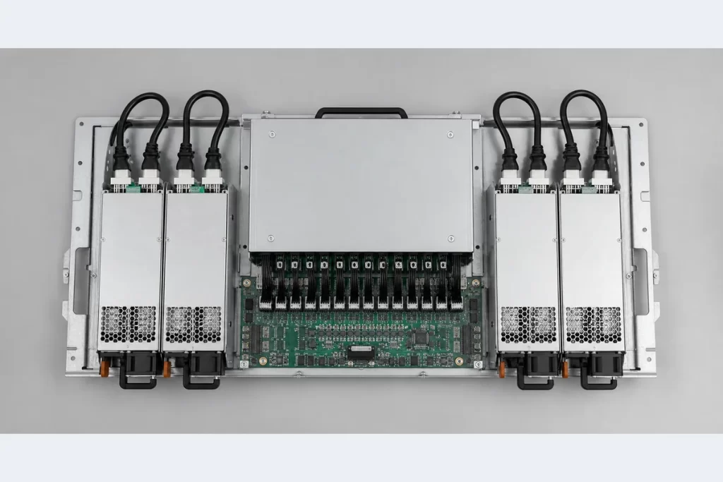
A four-module cage may feed one common bus, two semi-independent buses, or separate node domains. Each arrangement changes the meaning of failure. On a common bus, isolation and current sharing prevent one bad module from pulling down the others. With two power domains, the system may preserve a subset of nodes or load zones after one side is lost. A multi-node chassis can advertise enclosure-level redundancy while still having internal dependencies that determine which nodes remain available.
Trace the path through the power distribution board, busbars, branch connectors, harnesses, and local converters. The copper and protection devices must carry the maximum current created by the selected surviving state. A 2+2 policy can move a much larger fraction of total load onto one feed-side path after a group failure. Connector temperature rise and voltage drop should be evaluated in that state, not only under balanced four-module operation.
Management must agree with the copper. The BMC needs accurate presence, health, input, output, and fault information for each module. If the platform applies a power cap after losing a module, the transition from detection to throttling must occur within the supported energy and thermal envelope. Telemetry is valuable for observing the event, but fast electrical protection still belongs in hardware.
Failure redistributes heat as well as watts
Four installed modules share conversion loss and airflow during normal operation. When one or two modules disappear, surviving converters move to a higher load point and may produce more heat per module. Their fans may accelerate, while an empty bay or stopped fan changes chassis pressure. In a dense 4U GPU server, the PSU region and accelerator region compete for the same rear-panel area and airflow budget.
Blanking pieces, air baffles, seals, cable routing, and module airflow direction should remain correct for every supported population. Operating a three-module configuration in a four-bay cage may require a blank in the unused bay. Removing a failed PSU for an extended period can create a recirculation path even if electrical redundancy is intact.
Thermal controls can also reduce available electrical capacity. Module derating, fan-failure policy, high inlet temperature, and altitude may lower the load a surviving set can sustain. The redundancy state table should therefore pair each allowed module state with its cooling configuration and host power limit.
The operating policy is the architecture’s final layer
Modular hardware creates choices that software must manage consistently. Define what happens after one module fails, one feed disappears, two modules in a supported group are lost, a replacement is inserted, or module types differ. The platform may maintain full performance, apply a temporary cap, shut down selected accelerators, or refuse an unsupported mixed population. Those responses should be known before deployment rather than discovered during an outage.
Fleet operations also need an unambiguous healthy state. Four green module indicators do not prove that feeds are independent, the intended redundancy mode is active, or enough reserve remains. Monitoring should expose installed population, configured policy, present input groups, available capacity, and any degraded thermal condition. An alert should describe the service consequence—not merely report that a PSU is absent.
A 4U modular redundant server power system is complete when its module population, A/B feeds, load zones, distribution paths, cooling state, and host policy describe the same failure promise. The practical output is not a larger combined wattage number. It is a stated workload that the server can continue running after each supported module or feed event.