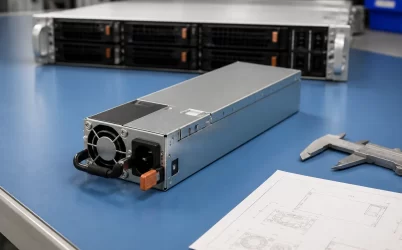
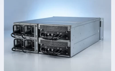
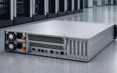
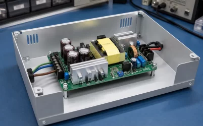
A server PSU pinout is specific to the power-supply model, revision, host platform, and mating power distribution board (PDB). There is no safe universal pin map for every hot-plug, proprietary, or CRPS-style module. Before assigning any contact, identify the exact PSU, record which side of the connector the drawing shows, and reconcile the information with the mating assembly. Similar shells, wattage ratings, and card-edge layouts do not prove electrical equivalence. A credible pinout separates documented facts from physical traces, measurements, inferences, and unresolved contacts; it also stops short of energizing the module when voltage, sequencing, or control behavior remains uncertain.
Quick answer: identify the interface before interpreting the pins
Start with the full module part number, revision, input type, host server, and mating PDB. Establish whether the reference view looks into the PSU connector, into its mate, or from the board side, because mating views are normally mirrored. Then classify only those contacts supported by evidence: main output, power return, standby power, presence or enable controls, status, current sharing, and management. Do not assume that a familiar signal name, connector shape, or CRPS description establishes its pin number, polarity, voltage, timing, or protocol behavior.
Pin numbering is a physical coordinate system
Many apparent pinout conflicts are actually orientation errors. A connector drawing can depict the PSU’s blind-mate face, the PDB connector facing the PSU, or the solder side of the mating component. A left-to-right sequence in one view becomes right-to-left in the opposing view. Row names may also change when a drawing is rotated.
Create an orientation record before copying assignments. It should include:
- The complete manufacturer and platform part numbers, including suffixes and revisions.
- A photograph of the module label and a wider photograph showing the entire PSU.
- A straight-on image of the connector with the module’s top, latch, handle, airflow direction, and insertion direction identified.
- The viewpoint used by each source: PSU face, mating face, component side, or solder side.
- Visible keying, unequal contact lengths, separated contact groups, and any numbering molded into the connector.
Do not create numbering from visual symmetry. A connector may have repeated high-current contacts on one side and smaller signal contacts on another, but their count and position do not establish their assignments. Longer or shorter contacts can support staged connection during insertion, yet contact length alone does not reveal which signal is sequenced or what timing the platform expects.
CRPS documentation also needs revision control. The Intel discussion of the Common Redundant Power Supply Design Guide is a useful reminder that interface information belongs to an applicable design document and revision. The term CRPS should not be treated as permission to transplant a pin map from an unidentified module.
Group contacts by function before naming pins. These categories organize evidence; they are not assignments for any particular module.
| Class | Possible role | Evidence required |
|---|---|---|
| Main output and return | High-current bus | Voltage, polarity, grouping, and limits |
| Standby | Auxiliary rail | Voltage, reference, current, and startup state |
| Presence, enable, or status | Control or reporting | Direction, active level, reference, and timing |
| Current sharing | Load division | Method, pairing rules, and fault behavior |
| Management | Telemetry or control bus | Levels, addressing, commands, and host requirements |
| Reserved or unknown | Unconfirmed | Leave unknown until exact documentation or trace evidence resolves it |
Do not equate DC return with protective earth or chassis; continuity may pass through bonding, filters, or sensing paths. A familiar signal label does not prove polarity, voltage, pull-ups, sequencing, or protocol. Confirm PMBus or SMBus behavior for the exact module, PDB, and host.
Build an evidence map, not a clean-looking guess
A pinout record should show how each assignment became known. This prevents a plausible diagram from acquiring more authority than its sources. Use one row per physical contact or bonded contact group, and retain unresolved entries rather than filling gaps by analogy.
| Record field | Purpose |
|---|---|
| Contact identifier | Connects the entry to a photograph or drawing with a declared viewpoint |
| Proposed function | States the main-output, return, standby, control, sharing, management, reserved, or unknown category |
| Evidence source | Names the exact datasheet, platform manual, schematic, board trace, or measurement |
| Applicable identity | Records PSU model, revision, PDB, host, and document revision |
| Evidence status | Marks the entry as documented, physically traced, measured, inferred, conflicting, or unknown |
| Electrical conditions | Records voltage domain, reference, direction, logic state, and timing only where established |
| Unresolved dependency | Identifies missing polarity, sequencing, pull-up, protocol, or load information |
The strongest evidence is documentation for the exact module and platform revision. A platform service manual can establish an approved replacement without disclosing every contact, while a PSU interface specification or PDB schematic may define the electrical behavior needed for integration. Documentation for a visually similar model can generate a question, but it should not close the corresponding row.
Physical inspection and unpowered continuity measurements can strengthen or challenge the documentation. For example, several large contacts may trace to the same heavy copper plane on the PDB. That can support the conclusion that they form one current group, but it does not establish the allowable current per contact or prove the bus voltage. A small contact routed through logic components may be a control or management signal, but its direction and electrical limits remain unresolved until supported by a schematic or controlled measurement.
The mating PDB supplies half of the pinout evidence
A hot-plug module’s connector exists to mate with a cage, backplane, or PDB. Examining the PSU alone can hide the relationships that make its contacts meaningful. The board reveals which high-current fingers join a common plane, where standby power enters the control circuit, which contacts reach the baseboard management controller, and whether current-sharing or fault-isolation components sit between the modules and the common server bus.
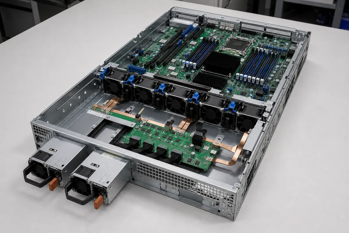
Trace both sides with the system unpowered and isolated according to its service documentation. Follow the PSU contact through the mating connector and into copper planes, fuses, ORing or isolation stages, standby converters, management circuitry, and downstream connectors where these elements are present. The goal is not to infer a complete schematic from appearance; it is to determine which source and load boundaries each contact can reasonably belong to.
This system view is especially important in a redundant pair. A contact described casually as “12 V” or “return” may be part of a parallel group whose integrity depends on every mating contact, the PDB copper geometry, and an isolation stage. Enable, presence, sharing, and management paths may also interact with both modules. Powernexu’s explanation of the 1+1 CRPS power distribution board provides additional context for how main power, standby, control, management, and fault isolation meet at this boundary.
Do not bridge an unknown signal to return merely because an online diagram labels a similar position as “enable.” The unknown contact could use another voltage domain, carry communications, participate in current sharing, or require a sequenced state.
Reverse engineering is a controlled last resort
Reverse engineering may be necessary when the exact interface documentation is unavailable, but it should narrow uncertainty rather than justify trial-and-error energization. Server PSUs connect to hazardous input energy and can deliver enough output current to damage tools, conductors, connectors, and circuit boards rapidly. Internal primary-side probing is outside the scope of connector identification and should not be attempted without qualified personnel, suitable equipment, and an approved safety procedure.
- Preserve identity. Record the PSU, host, PDB, firmware context, and every document revision before disconnecting the assembly.
- Document orientation. Photograph both mating faces and assign contact identifiers from one declared viewpoint. Create a mirrored mate view separately rather than mixing both perspectives.
- Inspect without power. Look for grouped heavy contacts, isolated signal regions, differing contact lengths, keying, and PDB trace destinations. Treat these observations as clues.
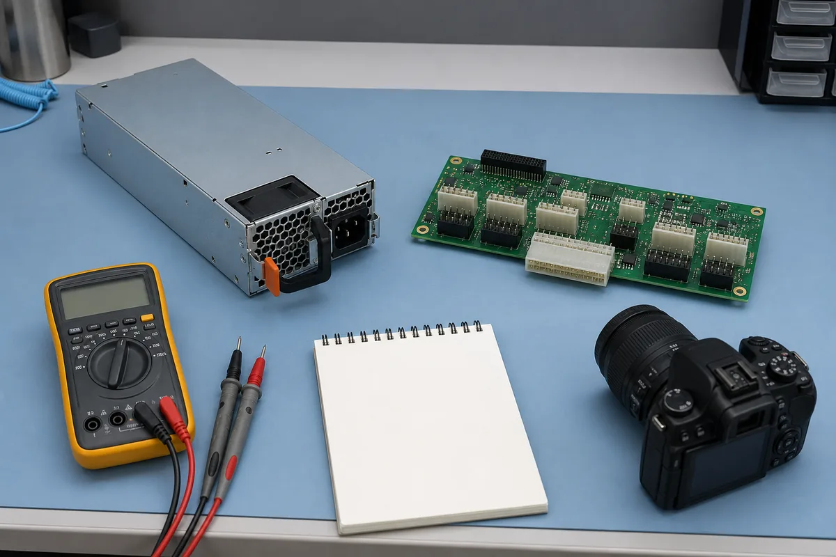
- Perform permitted continuity work. With all sources removed and stored energy handled under the service procedure, test only the paths needed to identify bonded groups or destinations. Record instrument mode and test points.
- Reconcile conflicts. If documentation and physical tracing disagree, check viewpoint, board revision, suffix, and the possibility that a signal passes through components rather than a direct trace.
- Escalate only under a defined plan. Energized characterization, if genuinely necessary, requires known input conditions, suitable protection, current-limited or otherwise controlled test equipment where applicable, appropriate loads, and predetermined stop conditions. It should not begin with shorting candidate contacts.
Voltage observed on an unloaded contact is not enough to establish its function. A standby rail may collapse under load, a logic signal may be pulled up weakly, and a communication line may appear as a steady level on a basic meter. Likewise, a main output that starts does not prove correct fault response, insertion sequencing, current sharing, or management behavior.
The required evidence depends on what the pinout will authorize
Not every use case needs the same degree of reverse engineering. The evidence should match the consequence of the decision.
| Intended use | Evidence that usually controls the decision | Reason to stop |
|---|---|---|
| Replacement in an existing server | Host-approved part number, documented supersession, revision and pairing policy, rather than a reconstructed pin map alone | The host does not approve the module, or the replacement identity remains ambiguous |
| Repair of the original PSU-to-PDB assembly | Exact assembly documents, connector orientation, trace evidence, and confirmed continuity of the original paths | Damage obscures the interface, or a signal’s role cannot be distinguished from a fault |
| Integration into a new PDB or platform | Complete electrical interface definition, sequencing, loading, sharing, protection, management, mechanical, and thermal information | Any required voltage domain, timing relationship, contact rating, fault response, or control behavior is unresolved |
| Standalone experimentation | A documented and controlled laboratory procedure for the exact module, including safe input, output load, control states, and stop conditions | The approach depends on a visually similar internet pinout or trial shorting of unknown contacts |
A replacement decision may be completed by authoritative host documentation even when the vendor does not publish the connector pinout. Conversely, a complete-looking community diagram may still be inadequate for a new PDB because it omits contact ratings, insertion sequence, share behavior, or fault handling. “The PSU turns on” is a much narrower result than “the interface is suitable for a server platform.”
Three questions that appearance cannot answer
Which pin turns on a server PSU?
There is no universal answer. Some modules expose an enable or remote-on function, but its contact, active state, reference, pull-up, sequencing, and relationship to presence or interlock functions are model-specific. Use the exact interface documentation or a controlled engineering record for that module and PDB.
Can two PSUs with the same connector use the same pinout?
Connector fit is not sufficient evidence. The modules may differ in output architecture, contact assignment, standby behavior, current-sharing method, management implementation, or revision-specific functions. A shell and card edge can remain visually similar while the electrical contract changes.
Can a multimeter identify the complete pinout?
No. Unpowered continuity testing can help locate bonded contact groups and PDB destinations, while controlled voltage measurements may characterize particular states. A multimeter alone does not establish dynamic sequencing, communication behavior, allowable loading, current-share stability, hot-plug response, or fault isolation.
Unknown contacts are a valid engineering result
The finished record should allow another engineer to reproduce the connector orientation, trace every assignment to its evidence, and see which questions remain open. Preserve the module and PDB revisions beside the diagram; otherwise, a correct map can later be applied to the wrong hardware.
A server PSU pinout is ready to support action only to the extent justified by its evidence. An approved replacement may require exact platform identity rather than full electrical disclosure. A custom PDB requires far more: verified power contacts, signal voltage domains, sequencing, sharing, management, protection, and mating behavior. If any function needed for the proposed use remains inferred or unknown, retain that status and stop before energization. A pinout with explicit boundaries is safer and more useful than a complete-looking diagram assembled from incompatible sources.