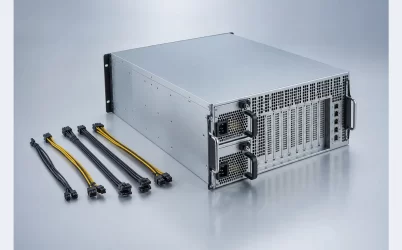
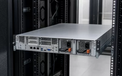
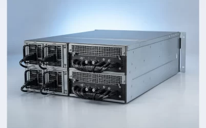
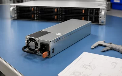
A 1+1 redundant CRPS power distribution board is the electrical junction that allows either of two Common Redundant Power Supply modules to support one server power bus after the other source is removed or fails. The PDB is not a passive cable adapter. It carries high current, limits reverse fault propagation, preserves standby and control functions, distributes power to several load zones, and influences whether the modules share current predictably. The correct board must match the CRPS interface, expected bus current, host outputs, cooling environment, and management design. If any of those relationships are undefined, installing two CRPS modules does not prove 1+1 availability.
The PDB turns two sources into one failure boundary
In normal operation, both CRPS modules may share the server load, or a platform may use another supported operating policy. In the degraded state, one module and its input path are unavailable. The surviving module must continue feeding the common bus through the PDB without the failed or unpowered path pulling that bus down. That is the core electrical promise behind 1+1.
The board sits at an uncomfortable intersection. Upstream, it mates with two high-current CRPS outputs and their standby, presence, sharing, and communication contacts. Downstream, it may feed the host motherboard directly or supply harness connectors for processors, storage, accelerators, fans, and auxiliary boards. A fault on either side can therefore reach a large portion of the server unless the distribution architecture contains it.
An Intel Server Chassis P4000M technical specification provides a concrete example: its documented PDB supports a 1+1 CRPS configuration and includes auxiliary conversion and additional overcurrent protection for 12 V rails. That is a platform-specific design, not a universal CRPS pinout, but it demonstrates why “PDB” can represent conversion and protection functions as well as physical distribution.
This makes the PDB a system-level component. Its relevant rating is not just total watts. The design must account for continuous current, load-step current, connector and copper resistance, branch protection, temperature rise, isolation-device behavior, control references, and the physical state of a module during insertion or withdrawal.
Two current paths must remain balanced before either one disappears
Current sharing protects capacity and temperature margin during normal two-module operation. If one path has lower resistance or a different control response, it can carry a disproportionate share of the load. The imbalance may begin at the module but can also be created by unequal PDB copper length, contact resistance, busbar joints, or sensing connections. A board that looks symmetrical in a photograph may not be electrically symmetrical.
The PDB impedance belongs inside the sharing analysis rather than being treated as an ideal zero-ohm connection. Exact sharing limits and methods must come from the CRPS specification and module documentation applicable to the chosen implementation. Resistance distributed through contacts and copper can alter both the static division of current and the response after a fast load change.
Resistance also converts bus current into heat and voltage drop. For a simplified hypothetical branch carrying 100 A through a total path resistance of 0.5 milliohm, the path dissipates about 5 W because loss equals current squared times resistance. The corresponding drop is 50 mV. Those values are not a universal design limit; they illustrate why milliohms matter in a high-current 12 V bus. Contact aging, assembly torque, copper temperature, and connector cycles can change the installed result.
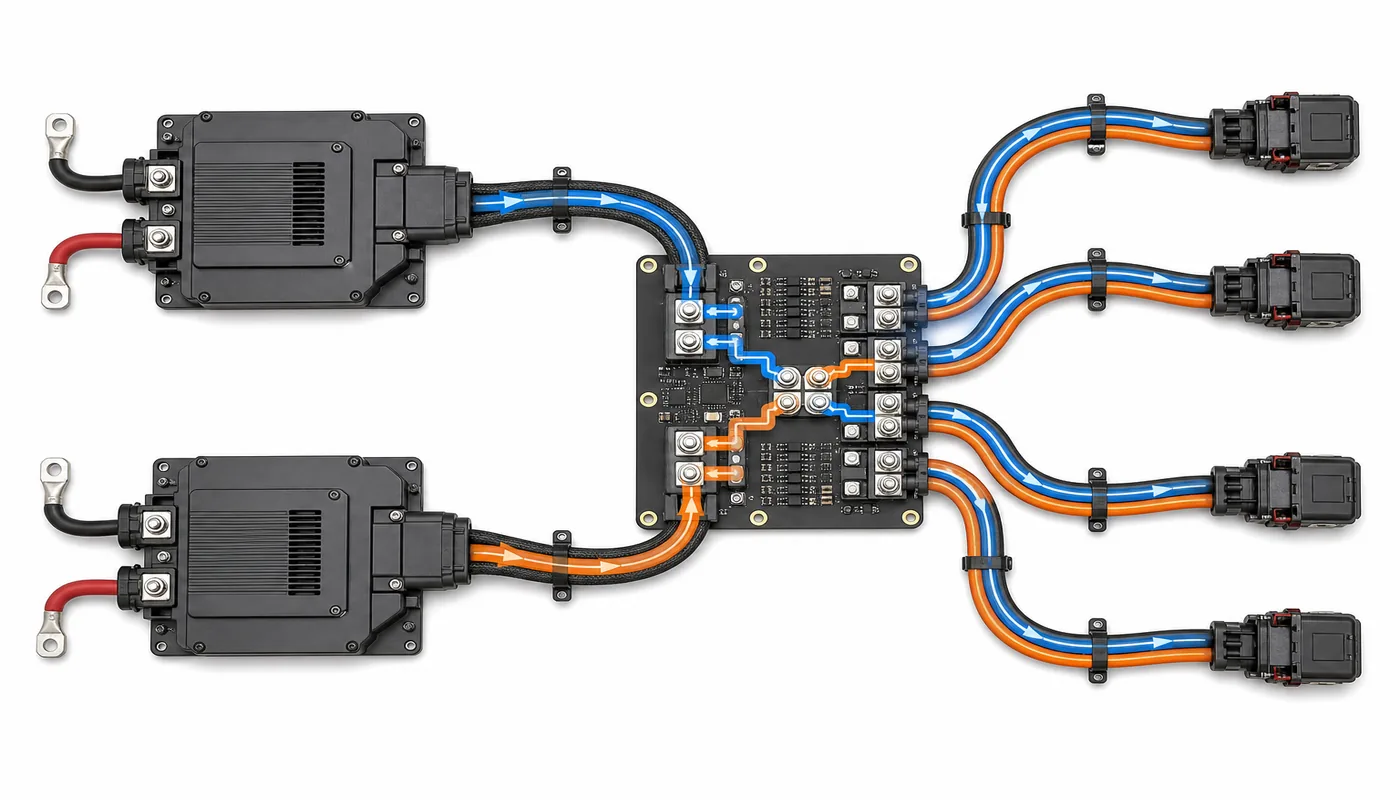
Isolation decides whether one fault remains one fault
When one source becomes shorted, unpowered, or partially connected, the healthy path should not feed destructive current backward through it. Server PDBs may use active ORing, module-integrated isolation, or another supported arrangement. The location matters because it determines which connector, copper region, and device remain exposed to a fault.
A PDB review should trace several states rather than assuming that “PSU failed” is one event. The module can shut down cleanly, develop an output short, lose its input, stop communicating, or be withdrawn under load. A connector may also pause in a partial-mate position. Each state presents a different combination of main output, standby output, share signal, presence contact, and parasitic path.
| Event | PDB behavior that matters | System consequence to examine |
|---|---|---|
| One AC feed is lost | Prevent reverse energy into the inactive source | Healthy module carries the required bus load |
| One module output shorts | Isolation and protection contain fault current | Common bus remains within the host operating boundary |
| A module is withdrawn | Connector sequence and isolation manage transition | No damaging arc, reset, or control-state corruption |
| One load branch shorts | Branch protection limits the affected path | Unrelated load zones are not unnecessarily lost |
This table defines questions, not guaranteed behavior. The supported fault response must be verified for the exact module, PDB, host, and protection scheme.
The common bus is only the beginning of distribution
Some CRPS systems deliver a primary bus, often 12 V in established server architectures, then generate or route other required rails elsewhere. Other PDBs include DC-DC conversion for auxiliary voltages, a standby path, or extensive output connectors. The product name alone does not reveal where voltage conversion or protection occurs.
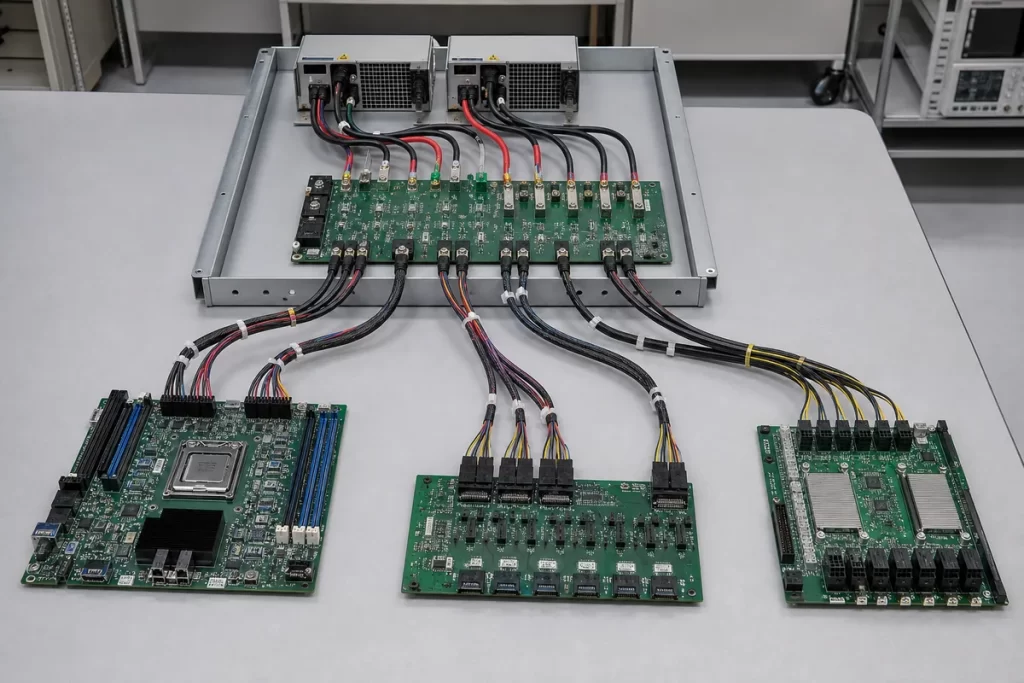
Start at each load zone and identify its source. The motherboard may need main bus power plus standby and control signals. Storage backplanes can add large start-up or rebuild loads. Accelerator branches can impose fast changes and high connector current. Fans and management controllers may need to remain available in states where the main compute load is off. If a PDB exposes several identical-looking sockets, their pin assignments and current limits cannot be inferred from appearance.
Branch protection should reflect the copper and connector downstream, not merely the total CRPS capacity. A pair of powerful modules can supply substantial fault current into a small harness. Fuses, electronic protection, connector ratings, wire gauge, and PCB trace geometry need a coordinated boundary. Splitting the load across more connectors may reduce current per contact, but only when the branches and return paths are designed accordingly.
Standby and management signals can defeat electrical redundancy
A server can retain main bus voltage yet still reset or become unmanageable if standby power or control signaling is interrupted. Presence detection, power-good behavior, enable signals, current-share references, and PMBus communication may pass through or terminate on the PDB. Their state during module loss is part of the availability design.
Management topology deserves a diagram of its own. Determine whether the BMC communicates with each PSU independently, through a mux, or through another controller. Addressing, alert handling, and bus isolation should allow the healthy module to remain observable when its partner fails or is absent. A short on a shared communication line can create a common-cause management fault even when the main power paths are isolated.
Telemetry also needs correct interpretation. Two module-current readings may not equal a calibrated measurement of every downstream branch. Rapid transients can be faster than monitoring intervals, and sensor location affects what the value includes. Use telemetry to detect imbalance, temperature trends, and module status, while relying on the documented protection and power-delivery design for fast fault response.
Mechanical fit controls contact quality and cooling
The board must hold two CRPS interfaces in the correct position while accommodating manufacturing tolerance, chassis flex, and repeated service cycles. Misalignment can concentrate force on connector contacts or prevent full seating. The cage, guide rails, latch position, board mounting, and connector support therefore form one mechanical stack.
High-current connections deserve particular attention. Inspect the supported mating connector, contact plating, engagement depth, board reinforcement, and the service-life assumptions supplied by the manufacturer. Cable pull and busbar stiffness should not twist the board or unload one side of a connector. Insulation, spacers, and keep-out distances must remain correct after the PDB is installed in the metal chassis.
Cooling cannot be assigned only to the PSU fans. ORing devices, DC-DC converters, connectors, copper joints, and protection components dissipate heat on the PDB. Their airflow may come from the server fan wall rather than the CRPS modules. A temperature probe placed in free air can miss a connector or semiconductor hotspot, while a cable bundle can shield the most heavily loaded region from airflow.
One plus one is proven at the load, not at the module handles
Imagine a server that requires 1,200 W at its defined sustained worst case and experiences a higher short transition controlled by the host power policy. Two modules each advertised at 1,600 W appear sufficient for 1+1, but that conclusion holds only if one module can deliver the required power at the site’s input and temperature, the PDB passes the required current, every critical branch remains powered, and the host tolerates the transfer. The board may impose a lower limit than the module label, and a particular output connector may impose a lower limit than the board total.
The decisive artifact is a fault-path map tied to the actual assembly. It should show both source paths, the combining and isolation points, standby and management paths, every critical load branch, and the protection boundary around each plausible fault. This is different from a generic procurement checklist: it explains how an event propagates through copper and controls.
If removing either CRPS module leaves all required load zones powered and managed within their supported conditions, the PDB is preserving the intended 1+1 boundary. If a shared connector, standby converter, communication bus, or unprotected branch can still disable the server, the drawing exposes where redundancy ends. The PDB earns its role by making one source failure remain local while the common load continues operating.