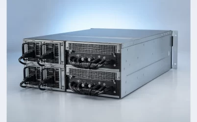
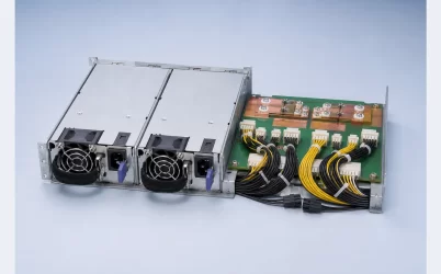
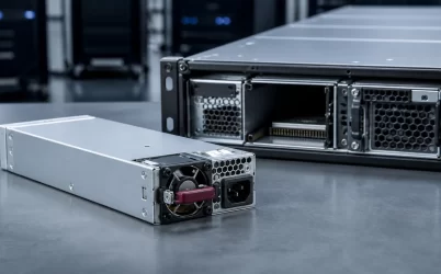
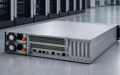
There is no single set of server PSU dimensions that acts as a universal replacement code. Length, width, and height can screen a candidate, but physical fit depends on the exact module and host assembly: body envelope, rails, flange, handle, latch, connector datum, insertion stop, airflow openings, and removal space. The reliable deliverable is a mechanical fit drawing that places the PSU and bay in the same coordinate system. It should compare maximum PSU boundaries with minimum available bay space, then show whether the module can travel through its full insertion and extraction path without interference.
Quick answer: document an envelope, not just three dimensions
A useful server PSU dimensional record separates the fixed metal body from everything that protrudes, moves, mates, or requires clearance. Establish common reference planes, normalize the PSU and chassis drawings to the same orientation and units, and record tolerances instead of comparing nominal values alone. Add the blind-mate connector location, guide geometry, hard stop, latch travel, ventilation keep-outs, and service path. If an official drawing is unavailable, physical measurements can support investigation, but they should not be treated as proof of host approval or connector engagement.
The metal body is only one dimensional boundary
A marketplace listing may reduce server PSU dimensions to three numbers, but those numbers can describe different things. One supplier may measure only the rectangular housing. Another may include the rear flange or extraction handle. A third may publish a shipping or product envelope without identifying its reference surfaces. Two apparently identical dimension sets can therefore represent different physical assemblies.
Divide the module into five dimensional categories before creating a comparison:
- Body envelope: the fixed housing boundaries, excluding movable or detachable features unless the source drawing states otherwise.
- Installation features: guide rails, locating tabs, keys, retention hooks, fastener ears, flanges, and other geometry that controls how the module enters or seats in the bay.
- Interface projection: the portion of a card edge, blade, connector shell, terminal, or other mating feature extending beyond the selected body reference plane.
- Moving envelope: the space swept by a latch, handle, release lever, or retention mechanism between its service and locked positions.
- Keep-out envelope: space that may be physically empty but must remain unobstructed for ventilation, electrical spacing, connector access, cable bending, or tool use.
The distinction prevents a common drawing error: treating a handle as extra module length while overlooking a smaller guide tab that actually determines whether the PSU can enter the bay. It also avoids the reverse mistake, where a bare housing fits inside the opening but a flange collides with the rear panel before the connector reaches its mating position.
Wattage and rack height do not resolve this ambiguity. Modules with similar ratings can have different shells, and a PSU installed in a 1U server is not necessarily as tall or wide as the chassis space surrounding it. Manufacturer documentation should control the lookup. For example, the Supermicro power supply matrix presents dimensions at the individual product level, illustrating why the exact model—not a generic “server PSU” label—must anchor dimensional work.
Choose reference planes before comparing drawings
Length, width, and height become meaningful only after their directions and origins are defined. Supplier drawings may show the connector end at the left or right, use a top view where the chassis drawing uses a bottom view, or assign width and height according to a different installed orientation. A mechanical fit drawing should therefore begin with a local coordinate system rather than relying on the words “length” and “depth.”
A practical convention is to assign one axis along insertion, one across the bay, and one vertically in the installed orientation. The letters used for those axes matter less than using them consistently. Add an airflow arrow separately; insertion direction and airflow direction are not necessarily the same.
Reference planes should correspond to physical events
Select datums that can be located on both the PSU and its host assembly. Depending on the design, useful references may include:
- the chassis rear-panel seating surface or another fixed bay entrance plane;
- the PSU flange or retention surface that establishes the fully seated position;
- the centerline or locating surface of a guide feature;
- the connector mating face rather than the end of an exposed contact;
- the PDB mounting plane or receptacle face inside the chassis.
Do not assume that the end of the metal housing is the insertion datum. In a hot-plug assembly, the final seated position may be controlled by a flange, stop, guide, or latch. The connector must then reach the intended engagement depth at that mechanically controlled position. A body-length match cannot demonstrate that relationship.
Record each measurement as a distance from a named datum. “Connector is 8 mm from the edge” would be incomplete even if the value were correct, because the edge, direction, and connector feature have not been identified. A controlled record instead states which plane is the origin, which connector surface is measured, and whether the dimension applies to the free module or fully seated assembly.
Normalize orientation, units, and drawing state
Before overlaying documents, place both drawings in the same installed orientation. Mirror a bottom view where necessary, but mark that transformation so a later reviewer does not mistake left for right. Convert units consistently without implying more precision than the original source provides.
Drawing state also matters. A removable module may be illustrated with its handle open, closed, or omitted. A chassis drawing may show the PDB without its mating receptacle, or it may represent a bare cage before rear-panel hardware is installed. State the configuration represented by each view. Otherwise, a clean overlay can still compare two different mechanical states.
Use tolerances to calculate the minimum available clearance
Nominal dimensions describe design targets; they do not describe every manufactured part. The fit question is whether the largest permitted PSU can occupy the smallest permitted bay while retaining the clearance required by the design. That requires tolerance information from the relevant mechanical drawings.
For a simple unconstrained axis, the first screening calculation is:
Minimum static clearance = minimum permitted bay dimension − maximum permitted PSU envelope
A negative result identifies an interference under the stated tolerance limits. A positive result establishes geometric space on that axis, but it does not automatically establish acceptable fit. Part alignment, coating thickness, guide tolerances, chassis deflection, thermal expansion, insertion angle, and the clearance needed to avoid binding may consume some or all of that difference.
Apply the calculation to functional features rather than only to overall dimensions. Examples include the separation between guide rails, vertical position of a key, flange-to-stop distance, connector centerline, and distance from the seating plane to the mating face. Asymmetric geometry should be measured from its datum, not converted into a centered width assumption.
If a drawing provides a bilateral tolerance, use the appropriate upper or lower limit for the comparison. If it provides a unilateral limit, preserve that direction. If no tolerance is stated, mark the field as unresolved rather than assigning an assumed manufacturing allowance. Physical measurement of one sample reveals the sample, not the permitted population.
Build the PSU-to-bay dimensional worksheet
Create one worksheet before CAD. For each item, record the PSU requirement, host boundary, shared datum, permitted limits, source drawing, and one result: pass, interference, evidence missing, or assembly-dependent.
| Drawing field | Minimum record | Decision |
|---|---|---|
| Identity and source | Exact model, revision, and drawing ID | Prevents cross-model comparison |
| Coordinates | Installed axes, orientation, units, and airflow | Aligns both documents |
| Static envelope | Maximum body and protrusions versus minimum opening and local restrictions | Screens interference |
| Seating interface | Guides, stop, flange, latch, and connector mating face | Tests alignment and engagement depth |
| Dynamic clearance | Ventilation keep-outs, adjacent hardware, handle sweep, and insertion and extraction paths | Tests assembly and service access |
An unknown connector datum remains evidence missing even if the shell fits. Use coordinated plan, elevation, rear, and connector-centerline views only where each reveals a decision; the worksheet, not drawing polish, is the controlling record.
The insertion path has dimensions of its own
A static CAD placement can hide an impossible installation. The PSU must move from outside the server to its seated position, and later travel back out for service. That swept volume can be larger than the final installed envelope.
Trace the module through the complete path. At the bay entrance, check whether the housing, keys, and connector projections clear the opening. Along the rails, inspect local restrictions caused by folded sheet metal, fasteners, harnesses, PDB supports, fan walls, or adjacent modules. Near final engagement, determine whether guides establish alignment before the connector begins mating and whether the latch can complete its motion without forcing the connector sideways.
Extraction requires a second view of the same geometry. The release mechanism must be accessible, the handle must deploy, and the module must move far enough to disengage before it needs to tilt or change direction. Rack doors, cable-management arms, rack posts, wall clearance, and rear-corridor restrictions can affect this service envelope even though they are outside the chassis drawing.
For height-constrained systems, extraction space and airflow can compete for the same rear-panel area. Powernexu’s article on 1U dual redundant server power supply integration examines that chassis-level relationship in more depth. The dimensional drawing discussed here has the narrower job of showing exactly where those boundaries lie.
Model moving features in at least their locked and service positions. If the mechanism follows an arc, a rectangular box around its endpoints may miss the maximum swept boundary. A simple path envelope or a few controlled intermediate positions can reveal interference that neither endpoint shows.
Resolve conflicts according to the evidence hierarchy
Server PSU dimensional research often produces conflicting numbers. A reseller page may list one length, the manufacturer matrix another, and a physical sample a third. Resolve the disagreement by identifying what each source measured rather than averaging the values.
- Confirm that every document refers to the same exact module, revision, and mechanical option.
- Prefer the current manufacturer mechanical drawing and host chassis documentation for controlled dimensions and tolerances.
- Use assembly drawings for relationships that a module drawing cannot establish, especially the PDB position, hard stop, guides, and neighboring hardware.
- Use a verified physical sample to investigate discrepancies, manufacturing state, or undocumented protrusions, while recording the instrument, reference surfaces, and uncertainty.
- Treat unsourced catalog dimensions as discovery information until their measurement boundary is explained.
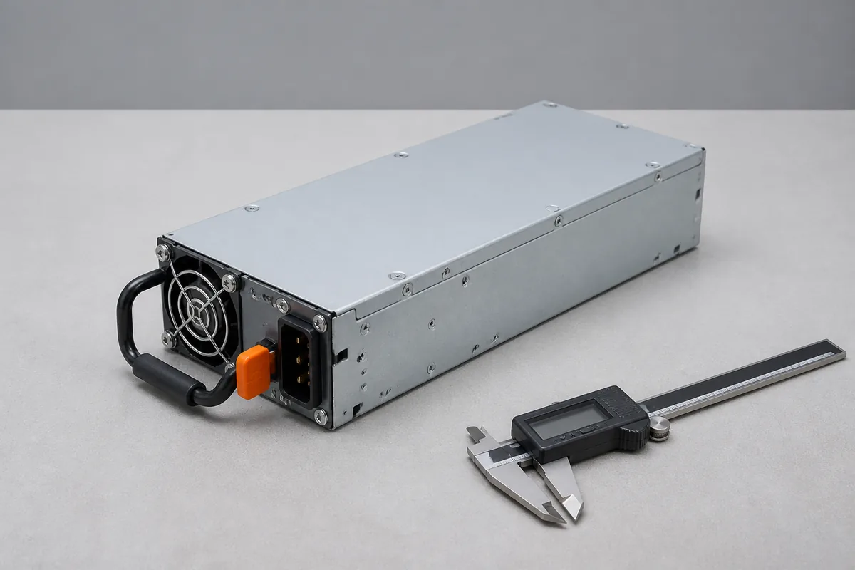
Measurements should be taken from a removed, isolated module using an appropriate safe procedure; server PSUs can retain hazardous energy after disconnection. Do not open the enclosure merely to establish external fit. Protect connector contacts and avoid using delicate interface features as caliper stops.
When evidence remains incomplete, annotate the drawing rather than silently filling the gap. A cloud around an unresolved keep-out zone, a missing tolerance flag, or a connector datum marked “manufacturer confirmation required” preserves the distinction between known geometry and assumption. That distinction is valuable during design review and supplier communication.
Where the dimensional drawing ends
A completed mechanical fit drawing establishes whether the module can occupy, enter, seat in, and leave the intended bay under the documented geometric conditions. It does not establish pinout, output architecture, control behavior, PMBus support, current sharing, redundancy policy, firmware recognition, thermal rating, safety approval, or host authorization.
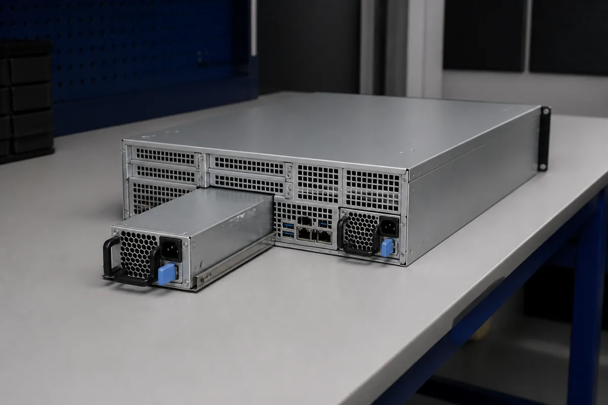
Those boundaries should remain separate. Passing the dimensional overlay allows the candidate to move into broader interface review; it does not convert a visually similar PSU into an approved replacement. Powernexu’s explanation of the broader server PSU form-factor ecosystem covers the electrical, control, cooling, and service relationships that continue beyond physical measurement.
The useful dimensional deliverable is compact and reviewable: named axes, common datums, source-controlled dimensions, tolerance limits, maximum protrusions, minimum bay boundaries, connector and seating planes, ventilation keep-outs, and the full insertion and extraction envelope. With those elements on one coordinated drawing, “Will this server PSU fit?” becomes a mechanical question that can be answered from evidence rather than appearance.