Server PSU form factors are compatibility ecosystems, not dimension labels. A usable match joins the module envelope to the chassis bay, guides, latch, extraction path, mating connector, output architecture, control signals, airflow direction, and service model. Terms such as ATX, Flex ATX, 1U, CRPS, and M-CRPS describe different levels of that relationship; they are not interchangeable shorthand. Before replacing or designing around a server power supply, identify whether the host expects a cabled fixed unit, a hot-swap module plus PDB, or a rack-level power shelf—and verify the complete interface defined for that platform.
A form factor is a contract with several layers
Searchers often expect a table of height, width, and depth. Those measurements can reject an obviously oversized supply, but they cannot approve one. A server PSU form factor works only when several layers agree: the metal envelope fits; the module follows the correct insertion and retention geometry; the power contacts meet the host at the intended location; the output and standby architecture match; control and management signals have the expected functions; and cooling moves in the direction the chassis was designed to support.
This explains why a narrow server module is not automatically “Flex ATX,” and why two units advertised as 1U can be incompatible. The rack unit describes chassis height, not a universal PSU interface. Vendors can package fixed cabled supplies, redundant cages, or proprietary hot-swap cartridges inside the same 1U system. Form-factor identification therefore starts at the assembly boundary: what exactly does the chassis accept, and which specification or support list defines that acceptance?
| Contract layer | Questions it must answer | What dimensions miss |
|---|---|---|
| Mechanical | Does the body enter, align, latch, and stop correctly? | Guide rails, keying, handle sweep, retention, connector datum |
| Electrical | Do input, output, standby, grounding, and current capacity match? | Rail architecture and contact allocation |
| Control | Do present, enable, power-good, sharing, and management functions agree? | Signal meaning, sequencing, firmware behavior |
| Thermal | Does air enter and leave along the host’s cooling path? | Airflow direction, impedance, fan control, recirculation risk |
| Service | Is it fixed, cabled, hot-plug, or part of a replaceable cage? | Live-removal behavior and access clearance |
The common families solve different packaging problems
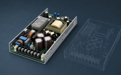
ATX-style supplies are cabled, enclosed units associated primarily with desktop and tower packaging. They can appear in workstation servers, storage systems, and 4U-class chassis where rear-panel area is less constrained. The mechanical mounting and cable set are central: motherboard, CPU, peripheral, and auxiliary connectors leave the supply on harnesses. “ATX” should not be used to imply server redundancy or hot-swap.
Flex ATX-style supplies use a much narrower cabled enclosure suited to compact computers and some shallow or thin rack systems. The phrase describes a packaging family, but products can still differ in length, harness arrangement, connector population, fan behavior, and output capability. A Flex ATX-looking unit cannot be treated as a universal 1U replacement.
Proprietary hot-swap modules are common in branded enterprise servers. They slide into a vendor-defined cage and mate to a PDB or backplane. Similar modules from adjacent server generations may use different keys, connector details, ratings, firmware, or pairing rules. The server service manual and supported-parts data own compatibility.
CRPS and M-CRPS modules move toward a documented common redundant interface. The Open Compute Project’s M-CRPS base specification defines a modular power-supply concept within the broader Modular Hardware System. That common specification can improve reuse across systems designed to the same revision and option set, but the acronym alone does not prove a particular module is accepted by a particular chassis. The host implementation, connector option, output configuration, management support, and approved module list still matter.
Power shelves and rack-level modules shift the boundary again. Instead of placing complete AC-to-DC conversion in every server, multiple front-end modules populate a shelf and feed a rack bus. Their form factor belongs to the shelf ecosystem: slot pitch, bus connection, shelf controller, input feed, output voltage, cooling, and redundancy policy are evaluated together. A shelf module should not be compared with a motherboard-cabled PSU merely because both convert AC to DC.
The module, cage, and PDB form one mechanical-electrical chain
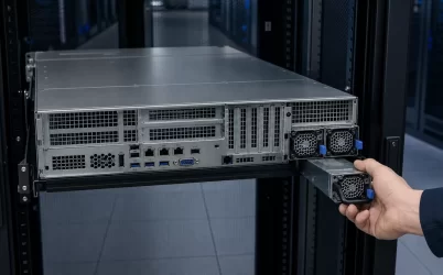
In a hot-swap system, the PSU body follows guides until its output connector reaches a defined mating datum. The latch supplies retention and often the final insertion force. The PDB receives high-current output, standby power, status and control signals, and sometimes PMBus/SMBus communication. Contact geometry and sequencing are designed around that motion. If the body is slightly shorter, a card edge sits at another height, or the latch closes before full engagement, the module may appear installed without making the intended connection.
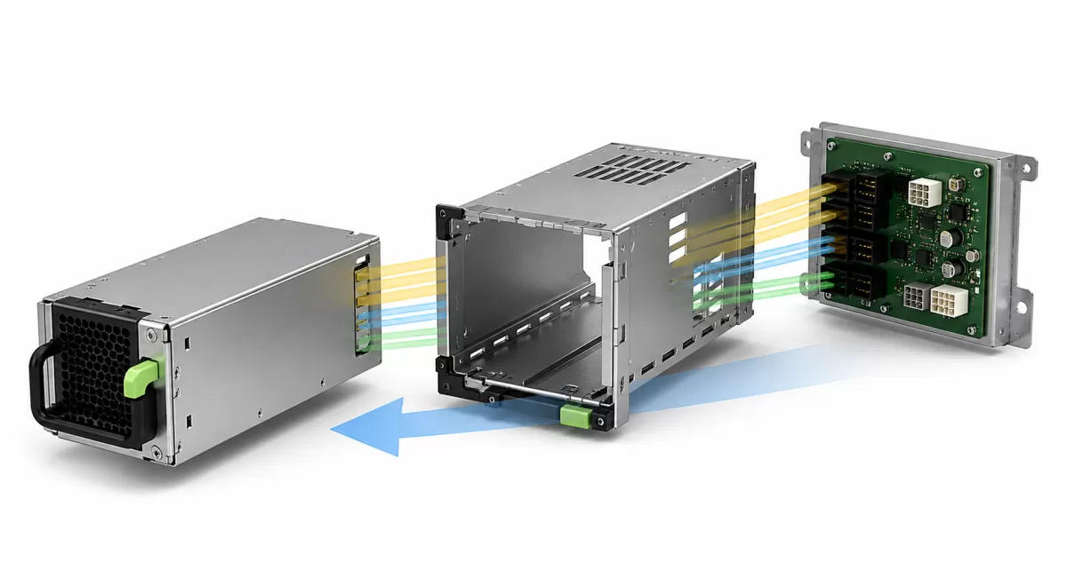
Electrical compatibility begins after mechanical seating. A common server architecture may provide a main DC bus and a standby output, but their values, tolerances, current allocation, pin functions, and control behavior are product-specific unless a shared specification fixes them. Remote-sense and current-share lines affect regulation across the pair. Presence, enable, and power-good signals tell the host what state the module occupies. Management communication can expose identity, input status, output telemetry, temperature, fan state, warnings, and faults, yet the exact command support is not safely inferred from connector appearance.
The practical implication is simple: never create an adapter by matching only large power contacts. An adapter also changes creepage, current density, grounding, signal sequence, fault isolation, retention, and airflow. A technically sound conversion would need an engineered interface and system-level safety and performance assessment, not just a cable map.
Chassis height influences packaging but does not name the PSU
A 1U server has limited vertical space. Designers often choose narrow modules, arrange two supplies horizontally, and place small high-speed fans in the module or system airflow path. Rear-panel allocation becomes a competition among PSU bays, network I/O, expansion risers, and ventilation. The extraction path must clear rack cable arms and PDU cords even though the chassis itself is shallow in height.
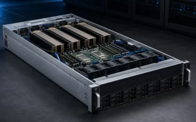
A 2U server offers more layout freedom. PSU bays may be stacked or placed beside expansion slots, and the chassis can accommodate a taller fan wall, more storage, and larger PCIe cards. That freedom does not mean any “2U PSU” fits. The power module may still be a narrow CRPS-style cartridge, a proprietary unit, or a fixed supply. The dedicated rackmount server power supply integration article explores bay placement and rear-panel constraints in more depth.
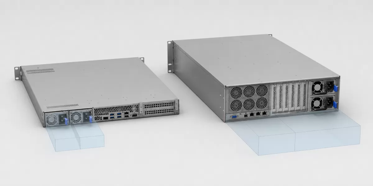
Depth deserves special attention because online listings often omit the system consequences. A longer module can interfere with fan walls, risers, drive backplanes, or cable bends even if its rear face fits the opening. A shorter replacement can leave the connector short of its mate or change the intended seal around the cooling path. Verify the mechanical drawing from the reference plane to the connector, not just the outer length quoted by a reseller.
Airflow is part of the interchangeability boundary
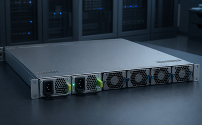
Server cooling is a continuous pressure path from the rack cold side to the hot side. A PSU’s fan and grille contribute impedance and local flow. Reversing the module airflow can oppose the chassis fans or recirculate heated exhaust into the system. Even modules with the same electrical rating can belong to different airflow options, particularly in network, telecom, and edge equipment where front-to-back and back-to-front deployments coexist.
Blanking and bay seals also belong to the form-factor ecosystem. An empty redundant bay may need an approved filler to prevent bypass air. The module face, cage walls, and internal ducting control where air travels. Replacing a supply with a smaller body and an improvised bracket can open a low-resistance path that starves processors, memory, drives, or accelerators downstream.
Fan control is another host relationship. Some modules regulate their own cooling from internal temperature and load; others exchange information with the system controller. Acoustic behavior alone cannot diagnose compatibility. A fan that runs at maximum may be protecting an unrecognized operating state, responding to missing management data, or revealing a thermal mismatch.
Standardization reduces options; it does not erase configuration
CRPS and M-CRPS are valuable because documented envelopes and interfaces can reduce custom engineering and improve supply-chain commonality. They also separate the removable conversion module from the PDB and downstream distribution. Powernexu’s CRPS architecture explanation covers that functional boundary, while the CRPS PDB assembly interface focuses on what remains in the host.
However, a standard can contain revisions, optional features, output variants, input variants, and mechanical choices. HPE’s current Modular Common Redundant Power Supply documentation is a useful real-world example: it describes an OCP-aligned form factor common across specified ProLiant Compute Gen12 servers while explicitly stating that it is not compatible with servers before Gen12. See the official HPE M-CRPS QuickSpecs. Standardization creates a defined compatibility domain; it does not make that domain infinite.
Identify the ecosystem before naming the replacement
For an existing server, record the exact host model and generation, PSU bay or cage assembly, installed module identifiers, connector type, input source, output architecture, airflow direction, and vendor-approved alternatives. For a new chassis, obtain the mechanical drawing, connector and pin specification, insertion and retention design, PDB requirements, cooling curve, management definition, safety evidence, and supported redundancy behavior. Compare documents at the assembly level rather than mixing a case drawing from one supplier with a module datasheet from another.
The phrase “server PSU form factor” becomes useful only after the boundary is explicit. ATX and Flex ATX usually describe cabled supply packaging; proprietary hot-swap modules belong to a server family; CRPS and M-CRPS describe more formal modular ecosystems; power-shelf modules belong to rack-level distribution. Dimensions open the compatibility investigation. The mechanical, electrical, control, thermal, and service contracts close it.