An adjustable open frame power supply should be selected by how its output must change, not merely by the presence of an adjustment potentiometer. First determine whether the application needs one-time local trimming, remotely commanded adjustment, or a genuinely programmable output. Then define the complete voltage window and prove that current, output power, accuracy, protection, startup behavior, cooling, and approvals remain valid throughout that window. A catalog entry that says “adjustable” without documenting these conditions is not enough to qualify the supply.
This distinction matters because commercial search results mix products with very different capabilities. Some allow a technician to correct a fixed setpoint during commissioning. Others accept a remote resistance or control voltage. A smaller group supports repeated setpoint changes as an operating function. These mechanisms solve different problems and should not be treated as interchangeable.
Quick answer: identify the adjustment mechanism first
Use local trim when the voltage will be set during assembly or commissioning and then left alone. Require documented remote trim when an external circuit must select or fine-tune the setpoint. Use a programmable supply when voltage must change repeatedly under machine or software control and controlled transition behavior matters. In every case, compare candidates at both ends of the required voltage range. Confirm the permitted current and power, load-side tolerance, sensing interaction, thermal conditions, protection thresholds, startup state, and response to a missing or invalid control signal.
One adjective hides three different control functions
Local trim corrects a mostly fixed setpoint
Local trim is commonly implemented with a potentiometer on the power-supply board. It can compensate for a required equipment setpoint, predictable distribution drop, or normal production variation. The available range is model-specific, and the adjustment may be intended for commissioning rather than frequent operation.
The mechanical location of the control is part of the requirement. A trimmer that becomes inaccessible after final assembly may be unsuitable for field calibration. Conversely, exposing an adjustment opening through the equipment enclosure can create access and safety concerns. The purchasing record should therefore identify who adjusts the control, at what production or service stage, and whether the power supply is energized during the procedure.
Remote trim moves adjustment away from the board
Remote trim allows an external component or control circuit to influence the output setpoint. Depending on the exact design, the interface might expect a resistance, a control voltage, or a manufacturer-defined trim network. Its reference point, permitted signal range, source impedance, isolation, failure state, and connection method cannot be inferred from the words “remote adjustable.” They must come from the exact model documentation.
Remote trim is also different from remote on/off. An inhibit or enable input changes whether the converter operates; it does not necessarily select its output voltage. Likewise, an auxiliary output or status signal does not establish setpoint control.
Programmable output is an operating capability
A programmable supply is expected to accept repeated setpoint commands as part of normal equipment operation. That creates additional requirements: command resolution, repeatability, slew rate, settling time, overshoot, response to rapid load changes, power-cycle behavior, and handling of communication or control faults. A local potentiometer driven by a makeshift actuator is not an equivalent substitute.
The word “programmable” also does not identify a universal interface. Control may be analog or digital, and some products require an optional interface or accessory. The quotation and bill of materials should state what implements the function rather than assuming that every required control is included with the base board.
Translate the load into a voltage-current window
The useful specification is a set of operating points, not a single nominal voltage. For each machine state, record the voltage required at the load terminals, the expected current, the permitted tolerance, the duration, and how frequently the setpoint changes. Include startup, normal operation, calibration, standby, shutdown, and fault recovery when they differ electrically.
| Required field | Question it must answer | Why it changes the shortlist |
|---|---|---|
| Minimum, nominal, and maximum voltage | What setpoints must the load actually receive? | Establishes whether the documented adjustment range covers the application. |
| Current at each voltage | Does the load behave as constant current, constant power, resistance, or a changing combination? | Prevents a nominal wattage rating from hiding an endpoint overload. |
| Load-terminal tolerance | How much error is allowed after regulation, trim accuracy, wiring drop, and temperature effects? | Shows whether adjustment resolution and regulation are adequate. |
| Adjustment frequency | Is the setpoint changed once, occasionally, or continuously? | Separates local trim, remote trim, and programmable operation. |
| Transition requirement | How quickly may voltage move, and how much overshoot can the load tolerate? | Determines whether static adjustment data are sufficient. |
| Startup state | Which voltage must appear before the controller becomes active? | Exposes systems that cannot rely on a command sent only after startup. |
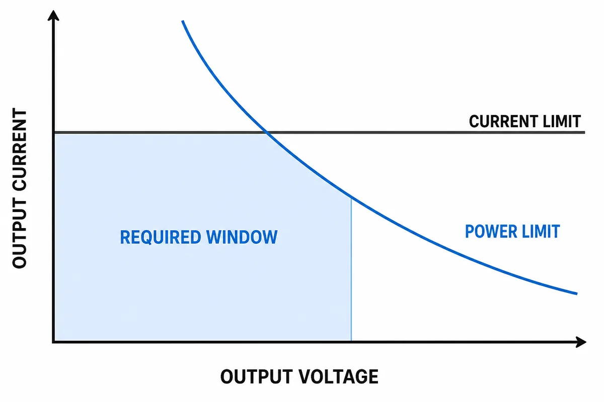
Consider a hypothetical load that requires 6 A throughout an adjustable 20–28 V range. Its output demand rises from 120 W at 20 V to 168 W at 28 V. A supply advertised at 150 W would not cover the upper endpoint unless its documentation permits the necessary output under the stated conditions. If the load instead consumes approximately constant power, current rises as voltage falls, which can make the low-voltage endpoint the limiting condition.
This is why voltage range, maximum current, and maximum output power must be plotted together. A candidate may be current-limited at the lower end and power-limited at the upper end. Do not assume that the full nameplate current is available at every adjustable voltage or that the highest voltage can be combined with the highest listed current.
Adjustment also does not replace DC distribution analysis. Wiring resistance creates a load-dependent drop, while trim establishes a source setpoint. If the project uses a nominal 24 V rail, the 24 V open frame power supply bus-design analysis explains how startup current, wiring drop, and load behavior shape the voltage that reaches the equipment.
Decode catalog language before assuming control capability
Distributor filters are useful for discovering products, but they often compress several functions into short attributes. Manufacturer family pages narrow the field further. For example, the TDK-Lambda open-frame AC-DC power supply families provide a primary-source starting point for product discovery. Qualification still requires the exact model datasheet, instruction manual, drawings, and applicable option documentation.
| Catalog term | What it may establish | What it does not establish by itself |
|---|---|---|
| Output voltage adjustment | The supply has some method of changing its setpoint. | The range, adjustment frequency, remote interface, or usable power at every setting. |
| Remote trim | An external network can influence the output on the documented model. | The control law, reference potential, isolation, default state, or dynamic response. |
| Remote sense | The regulator may compensate for some voltage drop between the supply and load. | A general-purpose programmable voltage input. |
| Remote on/off or inhibit | The converter can be enabled or disabled through a control input. | Adjustable output voltage while operating. |
| Programmable output | The setpoint can be commanded through a documented control method. | That every voltage transition, load condition, or failure mode suits the application. |
Remote sense deserves particular care. Sense conductors feed the load-terminal voltage back to the regulator so the supply can compensate for distribution loss within its documented limits. Combining maximum trim, maximum sense compensation, and light load may produce a different source-terminal voltage from the nominal setting. The exact manual should explain whether adjustment and sense compensation are cumulative, limited together, or subject to another restriction.
For multiple-output supplies, determine which rail is regulated and adjusted. Moving the principal rail may affect auxiliary outputs or cross-regulation. A product-family description cannot establish how every output behaves, so each required rail needs its own documented limits.
Compare exact models, not family labels. Record the documented adjustment method and option code, guaranteed voltage range, current and power limits at both endpoints, accuracy and regulation conditions, control input, remote-sense interaction, startup state, protection and recovery behavior, cooling or derating, and approval configuration. Mark missing evidence and omitted accessories as unresolved.
Test relevant control faults, including open, shorted, noisy, and out-of-range commands. Do not assume that protection thresholds track the setpoint or that loss of control causes a safe default. Qualify only behavior documented for the exact model under the intended input, load, and thermal conditions.
The exposed board changes how adjustment can be implemented
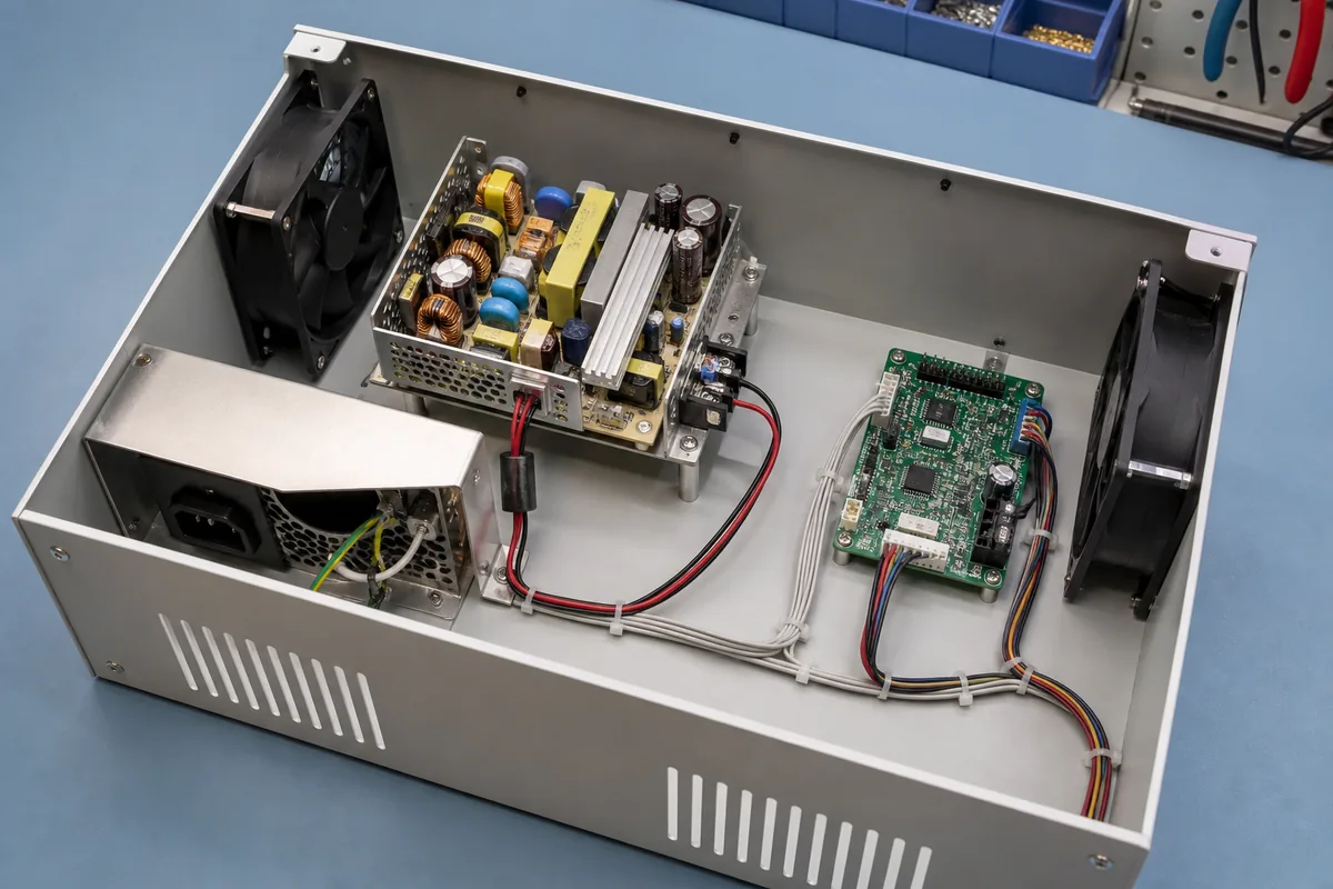
An open-frame converter transfers mechanical protection, access control, grounding, spacing, cooling, and final-equipment safety responsibilities to the host product. Adjustment introduces an additional access path into that design. A technician may need to reach a trimmer near energized circuitry, or a remote-control harness may pass through an electrically noisy part of the enclosure.
A local adjustment procedure should define enclosure state, tool access, shock protection, and whether energized adjustment is permitted by the equipment design. A remote interface should be routed according to its documented reference and noise requirements, away from conductors or switching nodes that could corrupt a low-level command. Do not assume the control input is isolated from the output or protective earth unless the exact documentation says so.
Cooling must also remain valid after the control hardware is installed. A daughterboard, wiring loop, service opening, or adjustment fixture should not block the airflow path on which the power rating depends. Mounting orientation and clearances need to preserve the conditions associated with the documented output envelope, especially if the upper setpoint creates the highest conversion or load power.
Match the test method to how often the voltage moves
One-time trim, remote trim, and programmable operation do not need identical tests. The test plan should resemble the intended use rather than applying a generic power-on check.
- For local trim: set the minimum, nominal, and maximum required points under controlled input and load conditions. Confirm load-terminal voltage, available current, physical adjustment access, and resistance to unintended movement after assembly.
- For remote trim: test the valid command range, endpoint tolerance, control-source limits, wiring sensitivity, startup default, and response to an open or shorted control connection. Exercise remote sense at the same time if both functions will operate together.
- For programmable output: run the intended voltage sequence with representative loads. Observe ramp rate, settling, overshoot, undershoot, command loss, power cycling, and transitions between load states. Average readings alone may miss a brief excursion that affects the load.
Production acceptance does not need to repeat every engineering test, but it should confirm the characteristics that can vary through assembly or configuration. These may include the final setpoint, option identity, control response, output at defined load points, and the default state after power cycling. Recording the exact model and revision prevents an approved adjustment profile from being applied automatically to a later substitute.
Adjustment frequency determines the appropriate product class
If the equipment needs a fixed voltage corrected during manufacturing, a documented local-trim supply may be the simplest answer. If service personnel or a supervisory circuit must change the setpoint occasionally, remote trim can remove the need to access an energized board. If voltage is part of the operating sequence, a supply designed and documented for programmable control provides the more appropriate starting architecture.
The requirement has moved beyond ordinary trim when the requested range is wider than the documented window, the control method is unsupported, endpoint current or power is insufficient, or the necessary startup and fault behavior cannot be achieved. At that point, use the custom open frame power supply design-boundary framework to separate a feasible platform modification from a new converter requirement.
The strongest purchase specification therefore does not ask only for an “adjustable” board. It names the adjustment mechanism, required voltage-current window, load-terminal tolerance, transition behavior, startup state, control-fault response, cooling condition, and evidence expected for the quoted model. That converts a broad catalog adjective into a measurable function the power supply can either support or fail to support.