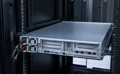
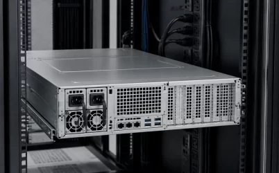
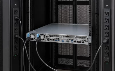
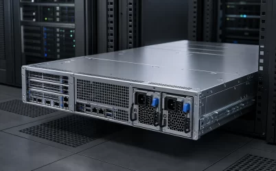
An industrial rackmount power supply should be specified as a rack subsystem, not selected from rack height and wattage alone. Before requesting a quote, define the upstream source, every protected load, operating and failure states, DC distribution, cooling path, service access, and the hardware included in the supplier’s assembly. Those boundaries determine whether the rack needs AC-DC or DC-DC conversion, a fixed supply or modular shelf, and module-level or wider power-path redundancy. They also prevent suppliers from quoting technically different products under the same broad rackmount description.
Quick answer: define the powered rack before the PSU
Start with a rack map that identifies where power enters, where conversion occurs, where output is measured, how it reaches each load, and what must remain operational during maintenance or a fault. Record normal, startup, transient, degraded, and shutdown states at those boundaries. Then specify the rack envelope, airflow, wiring, monitoring, redundancy scope, and service method. The resulting RFQ should identify the exact supplied assembly and request model-specific evidence for ratings, environmental limits, interfaces, protections, compliance, and included accessories.
Draw the rack boundary around five interfaces
The word “rackmount” establishes an installation context, but it leaves most of the electrical architecture unresolved. The supply could be a complete rack shelf, an enclosed converter attached to a tray, or a modular system containing removable power units and a shared distribution assembly. Its input might come from facility AC, plant DC, a battery-backed bus, or another conditioned source. Its output might feed industrial Ethernet switches, automation controllers, storage, instrumentation, embedded computers, or several load classes at once.
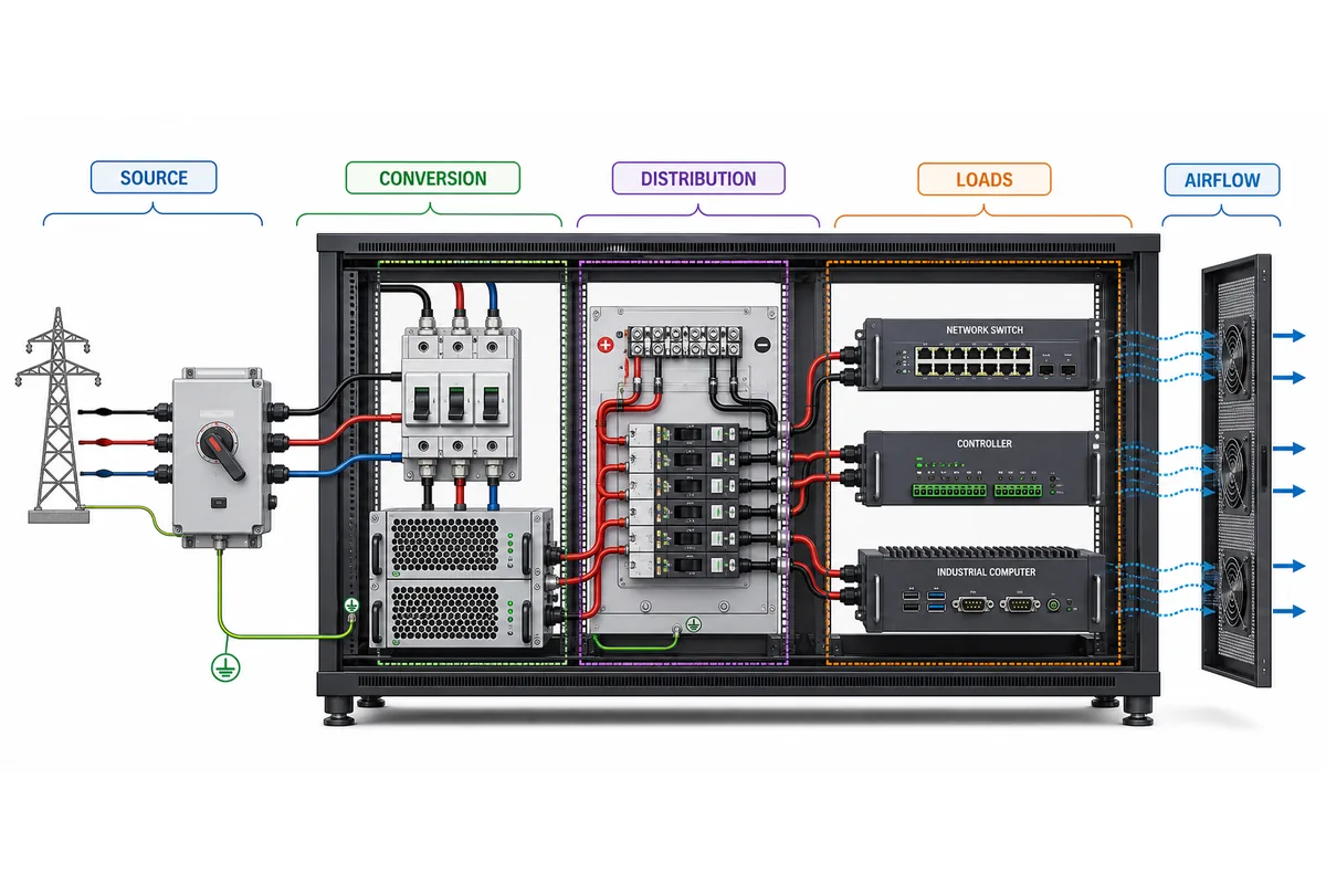
A useful rack map separates five interfaces:
- Source interface: the available voltage range, frequency where applicable, source polarity, grounding arrangement, protective device, connector, and credible source disturbances.
- Conversion interface: the rackmount power assembly, including its modules, shelf, controller, backplane, fans, and any hardware that the quotation may or may not include.
- Distribution interface: busbars, terminal blocks, harnesses, branch protection, disconnects, and the measurement point used for output ratings.
- Thermal interface: inlet-air conditions, airflow direction, exhaust destination, rack fan contribution, neighboring heat sources, and access to unobstructed ventilation openings.
- Load interface: the protected equipment, its accepted voltage window, startup sequence, dynamic behavior, grounding, and response to a brief interruption or controlled shutdown.
This boundary also assigns responsibility. A PSU supplier may document performance at the converter terminals while the rack integrator owns voltage drop through long harnesses, branch protection, airflow recirculation, and final-equipment EMC behavior. If the boundary is not drawn, both parties can make reasonable but incompatible assumptions.
Load states create the electrical specification
A nameplate total rarely describes the state that drives an industrial rack design. Automation and networking loads can start in stages, operate intermittently, reboot after a source event, or change demand when a communication link or redundant device is lost. Motor drives, capacitive inputs, battery chargers, and contactors may also create behaviors that are not represented by steady current.
| Rack state | Information to capture | Why it changes the supply requirement |
|---|---|---|
| De-energized to startup | Source application, load sequence, input inrush, load-side charging current, and permitted startup time | Simultaneous charging or poorly coordinated startup can operate protection or prevent an output bus from rising correctly. |
| Normal production | Coincident load at the PSU terminals, load diversity, duty cycle, and required output tolerance | This establishes the sustained operating point rather than a sum of unrelated maximum labels. |
| Fast load change | Step magnitude, rate, duration, repetition, and the load’s permitted voltage excursion | Average power can appear acceptable while transient response at the load is inadequate. |
| Degraded operation | Unavailable module, source, fan, branch, or load; remaining required functions; allowable derating | The surviving path may carry more current and reject more heat than it does during normal sharing. |
| Maintenance | Loads that remain energized, isolation points, removal path, and acceptable interruption | This determines whether fixed, plug-in, hot-swap, or externally bypassed service is appropriate. |
| Shutdown and recovery | Sequencing, stored energy, restart policy, alarms, and reset behavior after protection operates | A supply that shuts down safely may still require an unacceptable manual recovery procedure. |
Every value should name its measurement point. DC power at the converter output is not the same as AC input demand, and voltage at the PSU terminals is not necessarily the voltage at a distant load. Cable resistance, connectors, branch devices, and distribution boards create loss and voltage drop. If remote sensing is proposed, its permitted wiring, fault behavior, and compensation range must come from the exact model documentation.
Reserve should be tied to a reason rather than applied as an unexplained percentage. Possible reasons include a documented future load, lower available output at a specified temperature or altitude, a module-out condition, wiring loss, or a known transient. Combining all uncertainties into one oversized wattage allowance can conceal the requirement that actually controls the design.
Choose where conversion and serviceability live
The source and load buses determine the first architecture decision. An AC-fed rack supplying DC loads needs AC-DC conversion somewhere in the power path. A rack connected to a plant or telecom-style DC source may need DC-DC conversion when isolation, regulation, or a different load voltage is required. Some systems use a coordinated combination: a front-end converter establishes a rack bus, followed by local converters near sensitive loads.
| Architecture | When it can fit | Responsibilities that remain in the rack |
|---|---|---|
| Fixed AC-DC rack unit | Stable configuration with planned maintenance windows or external bypass | Input protection, output distribution, cooling, access, and replacement procedure |
| Fixed DC-DC rack unit | An existing DC source must be converted, regulated, or isolated for rack loads | Source polarity and range, grounding, upstream protection, distribution, and source-fault behavior |
| Modular power shelf | Capacity scaling, module replacement, or module-level redundancy is required | Shelf controller, combining and isolation method, module population, feed allocation, alarms, and spare policy |
| Distributed conversion | A rack bus serves several local converters near different load zones | Bus protection, local converter behavior, grounding, sequencing, and fault containment between branches |
Rack mounting and hot swap are separate attributes. Supplier category language reflects this distinction: TDK-Lambda’s rack-mount AC-DC category identifies rack installation and hot-swap capability as product-selection characteristics rather than treating them as synonyms. A removable module should therefore be described as hot-swappable only when the shelf, connector sequence, inrush control, isolation, controls, and service procedure support insertion and removal while the required load remains energized.
Likewise, a modular shelf does not automatically provide a required redundancy level. It can instead be used only for capacity scaling. The RFQ must state the intended module population, permitted unavailable components, and load that must remain supported in each degraded state.
Rack geometry is a working envelope, not a height label
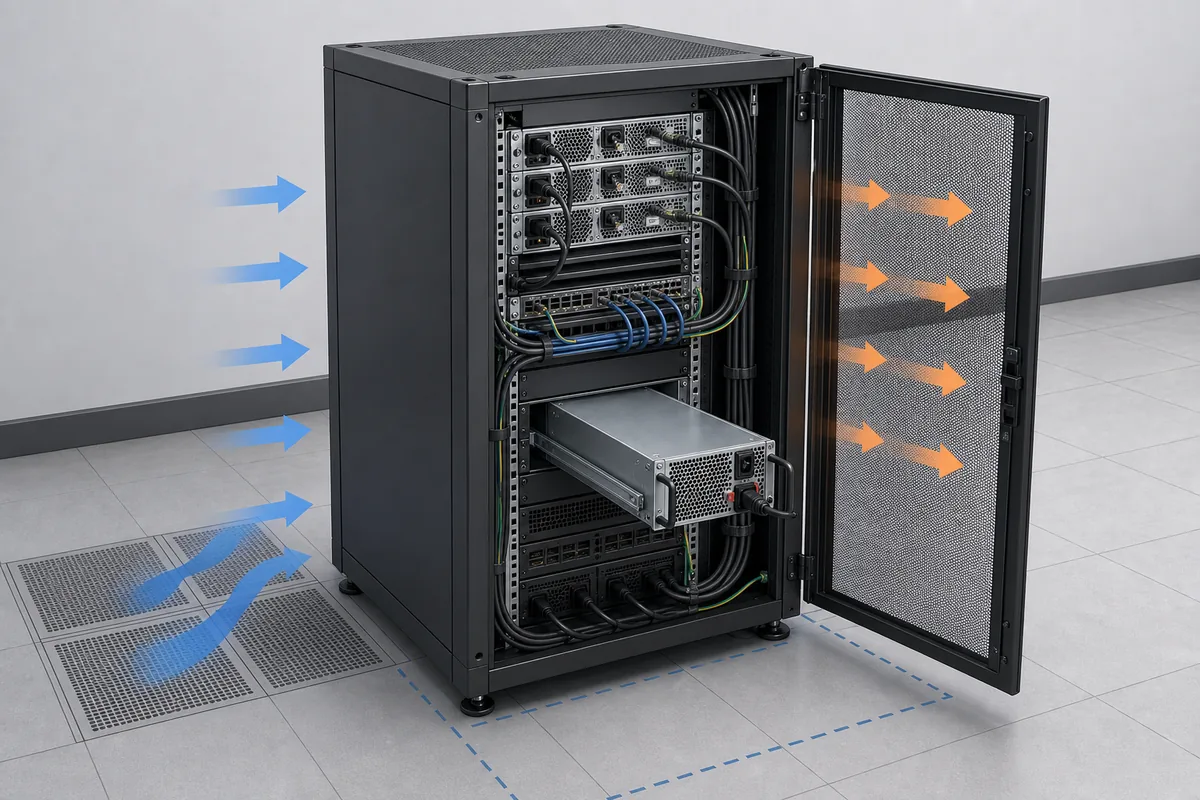
Rack-unit height is only one coordinate. The integration drawing must also include chassis depth, rail locations, front and rear protrusions, connector and cable-bend space, fan keep-outs, extraction distance, lifting or support needs, and access to protective devices. A unit that fits between rack posts can still be unserviceable if a rear door, cable manager, adjacent enclosure, or wall blocks module removal.
Placement influences both wiring and heat. Mounting a heavy conversion shelf low in the rack may help mechanical stability, but it can lengthen high-current DC routes to loads above it. Locating it near the load can shorten conductors while exposing the supply to hotter inlet air or obstructed service access. The preferred position follows from the actual rack layout rather than a universal top-or-bottom rule.
Cooling responsibility must be explicit. Determine whether the assembly has internal fans, depends on host-rack airflow, or uses both. Record airflow direction and the temperature at the actual PSU inlet, not only the room thermostat. Recirculated exhaust and heat from adjacent equipment can make the local condition substantially different from the ambient value reported elsewhere in the facility. Model-specific derating and airflow requirements should govern usable output.
For readers comparing rack terminology with server-oriented module dimensions, the server PSU form-factor ecosystem explains why an enclosure label does not establish the mating interface, airflow, or service contract. The same caution applies here, but the industrial rack boundary may include complete shelves, fixed converters, terminal distribution, and mixed automation loads rather than a platform-specific server bay.
Redundancy must name the failure it contains
“Redundant power” is incomplete unless it identifies the unavailable item and the loads that must survive. Two conversion modules sharing one AC feed protect against some module faults but not loss of that feed. Two source feeds entering one shelf may still share a controller, backplane, output bus, fan system, or downstream disconnect. Separate supplies can converge at one unprotected terminal block and recreate a single failure point.
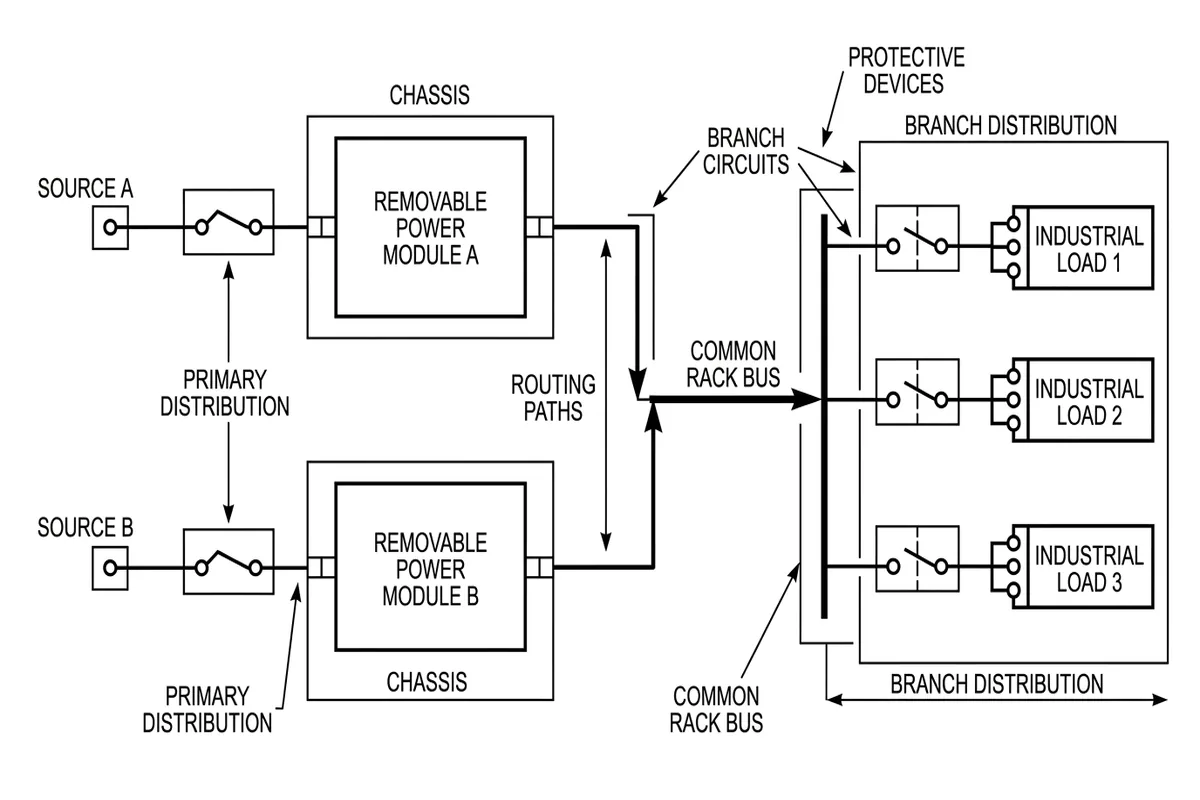
Define redundancy through explicit events:
- Loss or removal of one conversion module
- Loss of one upstream source or branch circuit
- Failure of a shelf controller or shared cooling component
- Short circuit or open circuit on one output branch
- Maintenance of a module, feed, disconnect, or distribution assembly
For each event, state which loads continue, for how long, and under what environmental conditions. If one remaining module must carry the complete protected load, its documented output under the deployed input and cooling conditions sets the module-out capacity. If the requirement is feed redundancy, the two paths must remain independent through the intended boundary; merely using two cords does not prove that independence.
Protection coordination matters because redundancy should contain a fault rather than transfer it to the common bus. Request the exact protection functions and their operating behavior, including whether a condition causes current limiting, hiccup operation, latching shutdown, automatic restart, or another response. Those behaviors are model-specific. The rack designer must then coordinate upstream and downstream protection so a branch problem does not unnecessarily remove every protected load.
Make every bid describe the same rack assembly
Use one comparison record so suppliers quote the same boundary while remaining free to propose different internal topologies. Each response should identify the exact model, applicable operating conditions, supporting document, and any unresolved exception.
| RFQ record | Required content |
|---|---|
| Supply scope | Modules, shelf, controller, rails, distribution hardware, cables, connectors, accessories, and exact model identities |
| Electrical boundary | Source type and range, grounding, feed arrangement, required outputs, load states, measurement points, startup behavior, and protection response |
| Environment and cooling | PSU inlet temperature, altitude, contamination, shock, vibration, airflow direction, derating, and cooling responsibility |
| Failure and service | Permitted unavailable components, supported load in each degraded state, isolation points, replacement method, restart policy, and spare identity |
| Monitoring and compliance | Required alarms or interfaces plus declarations, reports, certificates, and conditions for the exact quoted configuration |
| Commercial control | Itemized inclusions and exclusions, lifecycle status, warranty, change notification, and replacement policy |
Do not transfer a compliance mark from a related component or differently configured shelf without applicable evidence. Converter documentation also does not close final-rack duties such as protective bonding, touch protection, branch protection, wiring, accessibility, and EMC integration. Powernexu’s discussion of industrial-grade power-supply evidence provides the broader evidence framework; this RFQ should apply it to one named rack assembly.
Require exclusions to be as explicit as inclusions. A module-only quotation is not commercially comparable with a deployable shelf that includes rails, controllers, mating connectors, communication accessories, and output harnesses.
Carry the rack map into receiving, installation, and handoff. Reconcile model and revision, module count, accessories, and drawings with the accepted quotation. Preserve documented airflow orientation, cable clearance, protective bonding, branch protection, and service access. Keep monitoring-point names aligned with the load-state record so each alarm has an operational meaning.
Keep unresolved conditions open. Unknown inlet temperature, unfinished DC harnesses, unsupported startup demand, or undocumented shared components require measurement, supplier evidence, a distribution change, or a revised operating state.
The deliverable is an orderable architecture with a named source, load boundary, rack position, cooling path, distribution owner, service method, and failure scope. It should let suppliers quote consistently, integrators preserve assumptions, and operators know what remains powered outside normal operation.