Data center server power supply requirements should connect the workload to every upstream power boundary: server DC demand, PSU AC input, rack PDU allocation, UPS capacity, facility source, and cooling. The practical deliverable is a source-controlled requirements matrix in which every power figure has a measurement point, operating state, owner, and supporting evidence. This prevents DC load, AC input, redundant reserve, and infrastructure capacity from being combined as though they were interchangeable values.
Quick answer: Begin with the server states the data center must support, including normal operation, workload peaks, startup, module loss, feed loss, maintenance, and recovery. Convert each state’s DC demand into PSU input using efficiency data for the relevant operating point. Reconcile that input with cord, rack PDU, UPS, cooling, and redundancy limits. Then assign each requirement to the PSU, PDB, host platform, rack infrastructure, cooling system, or operations team and retain evidence for the deployed configuration.
Put every power figure on a named boundary
A server power number is incomplete until its location is identified. A processor or accelerator power estimate is not the same as power delivered by the PSU. PSU output is not the same as AC input, and AC input at one server cannot be compared directly with facility capacity without accounting for the rest of the rack and upstream infrastructure.
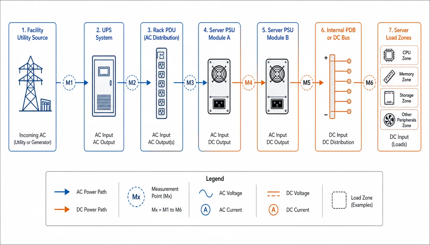
A useful boundary map contains at least five measurement planes:
- Load-side demand: the power consumed by processors, accelerators, memory, storage, fans, and point-of-load conversion stages.
- PSU DC output: the regulated power delivered to the server distribution system, including the main bus and any standby outputs.
- PSU AC input: DC output plus conversion loss at the applicable input voltage, load, temperature, and redundancy state.
- Rack input: the combined demand of the installed servers, network equipment, storage, and other rack loads at the rack PDU.
- UPS or facility boundary: the infrastructure capacity serving one or more racks, subject to topology, circuit allocation, operating policy, and required reserve.
The matrix should identify whether a value is measured, calculated, taken from controlled documentation, or estimated. It should also state whether it represents a steady load, short-duration event, conditional rating, or infrastructure limit. This distinction is especially important when one team supplies server telemetry, another sizes rack circuits, and a third owns UPS capacity.
The ENERGY STAR Version 4.0 Computer Servers specification provides formal server energy-efficiency definitions and test conditions. Those definitions can support consistent equipment evaluation, but they do not replace a deployment model covering the rack, UPS, failure states, or site operating policy.
Operating states become the rows of the matrix
A single peak wattage does not describe the events a data center power path must carry. Requirements should instead be organized by operating state. The list depends on the platform and continuity objective, but the following states expose many common gaps.
| Operating state | Power-path question | Required evidence |
|---|---|---|
| Normal steady operation | What input does the server draw across its representative workload range, and how is load shared between installed PSUs? | Server configuration, workload profile, rack PDU or server input measurement, and PSU operating mode |
| Workload peak or transient | Can the PSU, PDB, downstream branches, and upstream source tolerate the event without an unwanted shutdown or protection trip? | Workload-relevant power capture, platform limits, protection behavior, and applicable transient documentation |
| PSU module unavailable | What load transfers to the remaining module or modules, and does usable output remain sufficient under actual input and thermal conditions? | Redundancy topology, conditional module rating, host response, and degraded-state observation |
| Rack feed unavailable | Does the intended load remain energized through a genuinely separate source path, or do both cords eventually reach one common failure point? | As-built one-line diagram, PDU circuit assignments, UPS path identity, and feed-loss response |
| Startup and recovery | Do inrush, staggered startup, fan acceleration, and workload restart create a larger infrastructure event than steady operation? | Startup sequence, input-current behavior, PDU and UPS observations, and recovery policy |
| Planned service | What capacity and cooling remain while a PSU, feed, PDU, or upstream component is isolated? | Maintenance procedure, permissible load, alarm behavior, and service ownership |
These states should describe both electrical behavior and the expected service outcome. “The server stays online” may be the objective for a PSU replacement, while a controlled workload reduction may be acceptable during maintenance of an upstream feed. If the operating policy depends on power caps or workload migration, those controls belong in the matrix as requirements rather than informal assumptions.
Keep four capacity quantities separate
Track server DC demand, PSU AC input, redundancy capacity, and upstream infrastructure capacity as separate fields. Each value needs a measurement boundary, operating state, source, and applicable condition.
Convert DC demand at the applicable operating point
For state s and active module i, calculate total PSU input as:
PAC,total,s = Σ(PDC,i,s ÷ ηi,s)
For one active module, this reduces to DC output divided by its efficiency. For several modules, use each module’s actual load share and state-specific efficiency rather than one badge value. Conversion loss equals total PSU AC input minus total PSU DC output. Powernexu’s server PSU efficiency analysis explains the load-curve and heat relationship.
Translate watts into source constraints
For a planning estimate on a single-phase input, current ≈ real input power ÷ (RMS voltage × power factor). Final allocation must still follow documented input, inrush, connector, branch-protection, and PDU limits; an average-current calculation does not qualify the complete path.
Build the rack total from credible coincident states
Model the server states that can occur together instead of summing all PSU nameplates or relying on averages. Use diversity only when workload placement, power caps, or orchestration enforce it. Keep growth allocation and infrastructure reserve separate from the capacity reserved for a defined PSU or feed failure.
Assign each requirement to the interface that can satisfy it
The facility-to-server matrix becomes useful when every requirement has an owner. A PSU cannot compensate for an undersized rack circuit, and a dual-cord server does not create independent feeds if both cords terminate on the same upstream path. Similarly, a rack PDU can report server input but cannot establish whether the internal PDB is distributing current safely to every load branch.
| Boundary | Requirement fields | Primary handoff evidence |
|---|---|---|
| Facility source and UPS | Nominal source, permissible variations, available capacity, continuity objective, bypass state, and protected failure domains | Electrical one-line diagram, UPS operating policy, capacity record, and source-event definition |
| Rack PDU and branch circuits | Input source, outlet and branch allocation, usable current or power limit, metering, alarms, and A/B path identity | Rack elevation, circuit schedule, PDU configuration, and monitored demand |
| Cord and server inlet | Mating interfaces, current and voltage suitability, retention, routing, service access, and source assignment | Controlled cord schedule and physical rack inspection |
| Server PSU | Host-approved identity, input envelope, usable output by condition, efficiency behavior, airflow, protection, telemetry, and replacement rules | Platform documentation, exact part and revision records, and configuration data |
| PDB and internal distribution | PSU mating interface, source isolation, current sharing, bus capacity, load branches, standby path, and fault containment | Assembly documentation and platform-specific distribution evidence |
| Server loads and firmware | Permitted hardware configuration, workload states, power caps, startup behavior, alarm thresholds, and response to degraded power | Bill of materials, firmware baseline, BMC data, and workload control policy |
| Cooling system | PSU inlet condition, rack airflow, heat rejection path, degraded-state cooling, ambient limits, and environmental derating | Thermal design record, sensor locations, airflow configuration, and environmental observations |
| Operations and service | Alarm response, maintenance sequence, spare identity, allowable degraded duration, escalation, and restoration criteria | Runbook, asset records, approved spare list, and event history |
The internal distribution row deserves particular attention in modular servers. The PSU rating reaches the processors, accelerators, fans, and storage only through the PDB, connectors, copper paths, and branch protection. A redundant PDB must preserve the load after the required source event and prevent a failed path from disrupting its partner. Powernexu’s article on the 1+1 CRPS power distribution board examines that combining and isolation boundary in more detail.
Redundancy and efficiency alter the same rack budget
Redundancy and efficiency are often documented as separate attributes, but both change the power presented to the rack. Consider a server with two active modules. During normal operation, the modules may share the DC load. If one module becomes unavailable, the surviving unit takes a larger share, moves to another efficiency point, and may draw more input current through one cord and one PDU branch. The server’s useful computing load may remain unchanged while the distribution of AC demand and heat changes.
The matrix should therefore identify:
- the required redundancy topology and the failures it is intended to tolerate;
- the supported server load in each degraded state;
- which modules remain active and how load transfers between them;
- the input source serving each module before and after the event;
- the effect on conversion loss, inlet temperature, fan demand, and branch loading;
- the policy used when remaining capacity becomes insufficient.
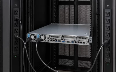
Two power cords should be traced through the rack PDUs, branch circuits, UPS paths, and maintenance bypass arrangements before they are described as independent A/B feeds. Independence is an infrastructure property, not a connector count. Conversely, a site may intentionally use dual PSUs on one feed for module serviceability without claiming protection against loss of that feed. The requirements matrix should record the actual objective rather than assign a broader meaning to the hardware.
Startup also crosses these boundaries. A restored rack can experience simultaneous PSU input charging, fan acceleration, storage spin-up, and workload recovery. If the design depends on staged startup, that sequence must be implemented and preserved by the responsible controls. Steady-state rack utilization alone cannot demonstrate recovery capacity.
Cooling and telemetry turn electrical limits into operating limits
Use model-specific input-voltage, inlet-temperature, airflow, altitude, and module-population limits; do not apply one assumed derating rule to every PSU. The matrix should distinguish:
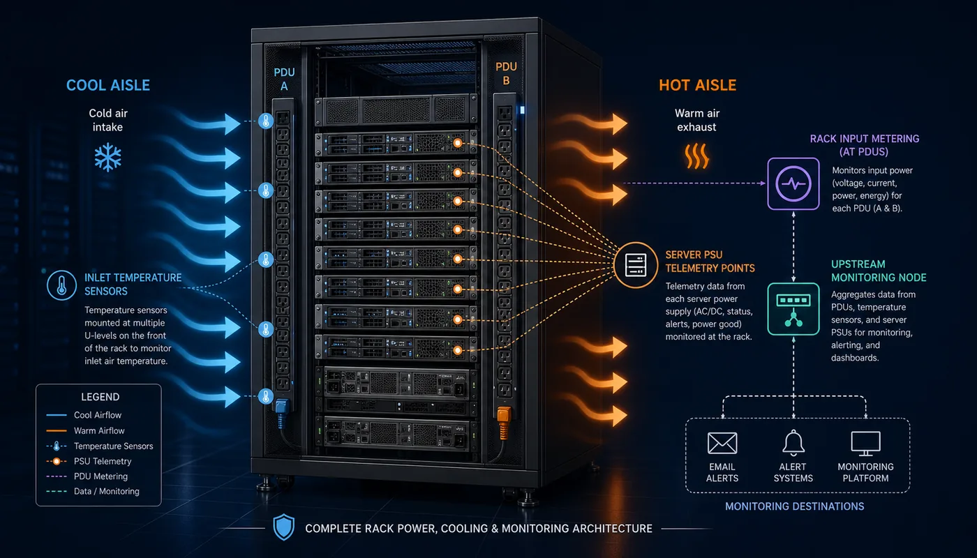
- PSU conversion loss: local heat produced by conversion.
- Total server input: the broader basis for server heat contribution.
- Heat-removal path: air, rear-door, liquid, or another facility path.
Include maintenance airflow states such as a removed module, open bay, or changed fan response. Identify every telemetry boundary: rack PDU data represents upstream input, while BMC or PSU data may represent module input, output, temperature, or an estimate.
For each alarm, record its source, threshold authority, delay, recipient, remaining redundancy state, and required response. Time-synchronized rack, UPS, and server records should allow an event to be reconstructed.
The handoff is complete when evidence follows the configuration
Keep the matrix attached to the configuration it describes. Hardware, firmware, power-cap, PDU, or PSU changes must trigger review of affected assumptions.
The acceptance package should retain:
- the as-built one-line diagram, rack circuits, and A/B source assignments;
- the server bill of materials, PSU and PDB identities, module population, and firmware baseline;
- controlled ratings with their input, thermal, airflow, and redundancy conditions;
- observations for normal load, required workload events, startup, recovery, alarms, and authorized fault states;
- measurement boundaries, sensor locations, instrumentation limits, spare identities, and service procedures.
Perform live-service or fault checks only when equipment documentation, site safety procedures, available capacity, and the continuity plan permit them. Otherwise, use applicable platform evidence or prior qualified results and record their limitations.
The matrix is complete when every required state has a supported path, every value names its boundary, every limit has an owner, and operations can retrieve the evidence for the deployed configuration.