A CRPS redundant power backplane should not be purchased from the word “backplane” alone. Before comparing quotations, define whether the supplier will deliver a bare circuit board, a power distribution board (PDB), an adapter, a populated cage, or a complete subsystem with CRPS modules and output harnesses. The RFQ must then connect that exact assembly to the intended CRPS module revision, mating interface, load paths, control signals, cooling conditions, mechanical envelope, and redundancy state. Acceptance should verify the documented configuration—not merely that the board looks correct or that a module can be inserted.
The most useful purchasing record has three parts: an assembly boundary that identifies everything included, an interface schedule that assigns every power and control connection, and an acceptance schedule tied to the quoted revision. Together, these records make technically different offers visible before price comparison begins.
The first RFQ line must name the shipped object
Suppliers do not necessarily use “backplane,” “PDB,” and “adapter board” for equivalent hardware. One seller may call a board with CRPS connectors and high-current buswork a backplane. Another may use PDB for the same general assembly but include branch connectors, standby conversion, monitoring, or protection. An adapter board may only translate between two physical interfaces, although its exact function still has to be documented.
The RFQ should therefore describe the deliverable by physical contents and functions instead of relying on the catalog noun. The supplier should be able to mark each item as included, optional, customer-supplied, or outside scope.
| Commercial description | Possible supplied boundary | Clarification required in the RFQ |
|---|---|---|
| Bare backplane | Unpopulated or populated PCB with CRPS mating positions | Connectors, buswork, active devices, mounting hardware, output terminations, and documentation |
| Power distribution board | CRPS input combining plus one or more host power branches | Isolation ownership, branch protection, standby functions, control signals, monitoring, and cable scope |
| Adapter board | Mechanical or electrical transition between interfaces | Whether it carries full load current, translates signals, provides protection, or only changes connector geometry |
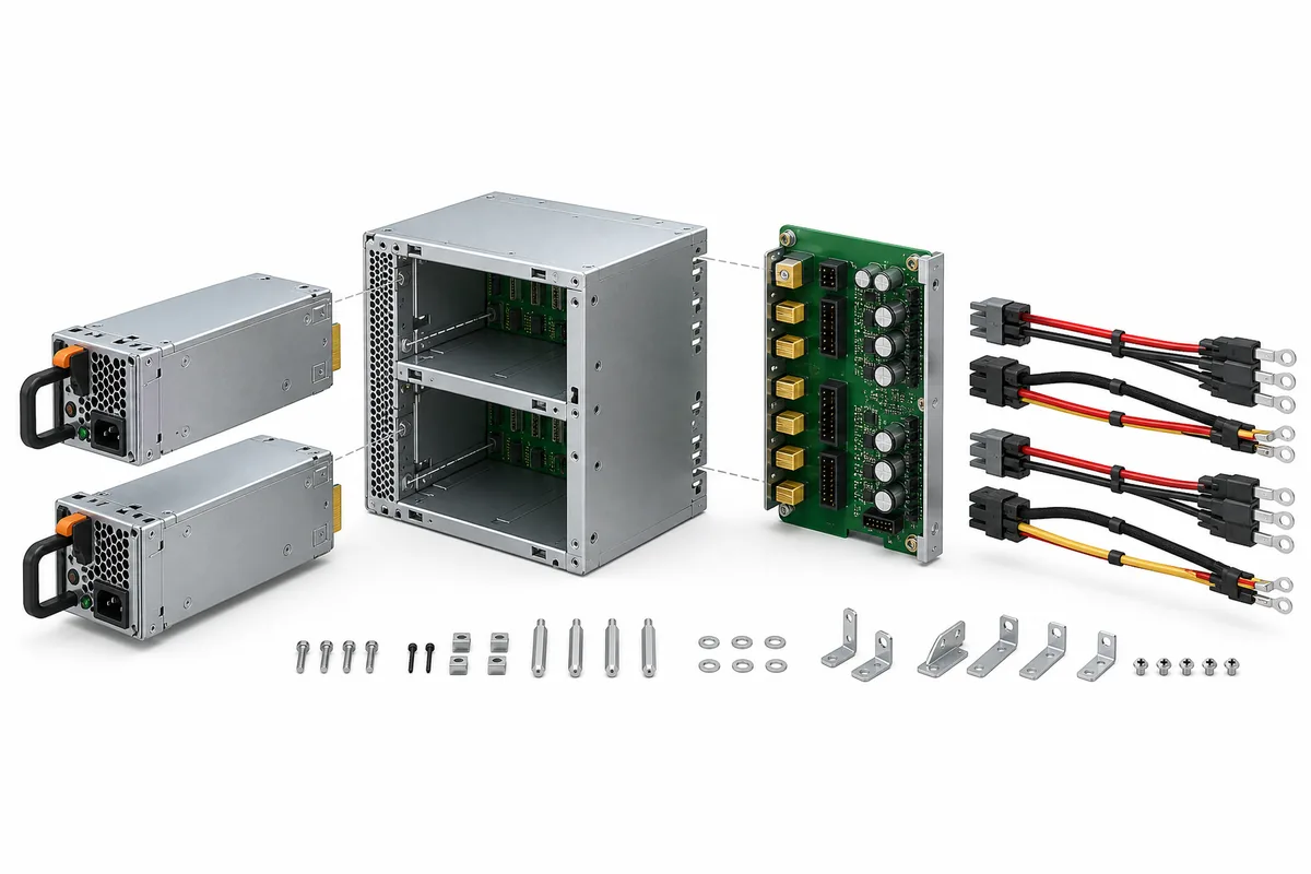
| Populated power assembly | Board, cage, connectors, guides, and associated hardware | Module quantity, harnesses, fans, fasteners, covers, firmware or address configuration, and installation parts |
| Complete CRPS subsystem | Power modules plus combining and distribution hardware | Exact bill of materials, supported operating mode, input accessories, host outputs, and exclusions |
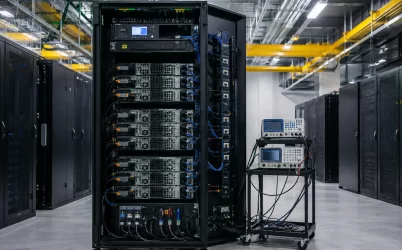
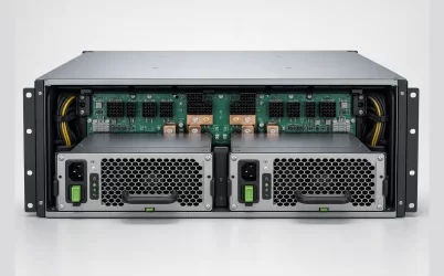
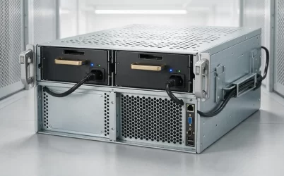
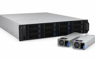
Photographs can help identify scope, but they are not sufficient configuration evidence. Request part numbers and revisions for the board, cage, connector assemblies, cables, and any supplied CRPS modules. If a quotation uses a family photograph, require confirmation that the depicted arrangement matches the line item.
Replace “CRPS compatible” with four controlled records
CRPS provides an industry design context for modular redundant power, but it does not make every module, PDB, cage, host, or firmware implementation interchangeable. Texas Instruments’ CRPS design resources illustrate the relevant redundant-power architecture and component functions; the exact commercial assembly still needs model- and revision-specific evidence.
1. Assembly boundary record
The assembly boundary record is a bill of material with responsibility attached. It should identify the quoted board, cage or bracket, CRPS modules, mating connectors, output harnesses, fasteners, airflow hardware, covers, and configuration accessories. It should also state whether drawings, pin assignments, management documentation, test reports, and integration support are deliverables.
This record prevents a common comparison error: pricing a module-only offer against a complete power assembly. It also exposes integration work that would otherwise appear after purchase, such as sourcing the cage, developing high-current output cables, or designing a host mounting plate.
2. Interface control schedule
An interface schedule names both sides of every boundary. For the CRPS connection, it should identify the exact module and board revisions, connector orientation, seating datum, keying, contact assignments, mating sequence where applicable, and supporting drawing. Power contacts, standby power, enable, presence, power-good, current-share, addressing, and management communication must remain distinct.
Do not infer a contact map from a visually similar board. The evidence required to interpret a server PSU connector boundary includes both mating assemblies and the host behavior expected from their signals. If the supplier cannot disclose a complete pinout, it should still provide enough controlled interface information to establish approved module compatibility and host integration responsibilities.
The downstream side needs the same treatment. List each output connector or bus interface, destination, voltage domain, return path, cable responsibility, and applicable current condition. A connector family name does not establish pin assignment, conductor size, contact population, or branch capacity.
3. Mechanical and cooling definition
The mechanical package should place the CRPS modules, cage, backplane, and host attachment points in one coordinate system. Useful evidence includes board outline, hole pattern, connector and seating planes, guide geometry, insertion stops, latch engagement, keep-out zones, module extraction path, and clearance for output connectors and cables.
Cooling information must describe the assembled state. Request module airflow direction, the board’s position relative to the airflow path, obstruction limits, relevant inlet conditions, and any forced-air dependency for high-current components or connectors. A bare-board rating obtained under unspecified airflow does not establish suitability inside a congested server chassis.
4. Function and responsibility matrix
The matrix should state which component owns each function. Reverse-current isolation, current sharing, hot-insertion control, inrush limitation, standby conversion, branch protection, fault reporting, and management access may reside in the CRPS module, the backplane or PDB, the host motherboard, or a combination of them. The allocation cannot be inferred safely from the word “redundant.”
For every required function, record the implementing component, controlling document, required host dependency, and evidence offered by the supplier. An unresolved function is not necessarily a rejection, but it must remain visible as integration work rather than being treated as an included backplane capability.
Electrical evidence must follow the intended operating state
A current rating is meaningful only when its measurement boundary and operating conditions are known. The supplier’s evidence should distinguish the total CRPS input path, combined bus, individual output branches, connectors, and cables. It should also state the applicable module population, input condition, airflow, ambient or inlet condition, board orientation where relevant, and allowable temperature limits used in the assessment.
For a 1+1 assembly, ask for the supported load and electrical behavior with both modules operating and with either specified module unavailable. The backplane must not be treated as acceptable merely because its aggregate copper appears capable of carrying the nominal total. The remaining module connection, combining path, output connector, return path, and cooling condition all participate in the degraded state.
The RFQ evidence schedule should address:
- supported CRPS module manufacturers, models, and revisions, without assuming family-wide interchangeability;
- continuous and transient conditions at each relevant electrical boundary;
- voltage drop and thermal behavior across connectors, copper, combining devices, and output branches;
- location and behavior of reverse-current blocking or ORing functions;
- current-share behavior and the conditions under which it is supported;
- standby power availability during startup, shutdown, module loss, and replacement;
- enable, presence, power-good, alert, and management behavior expected by the host;
- branch protection or fault-containment boundaries and the faults they are intended to isolate;
- hot-plug support, including connector sequencing, insertion conditions, and any host procedure required.
Detailed 1+1 fault propagation is a separate architectural question. Powernexu’s analysis of where redundancy lives in a CRPS PDB explains how isolation, common buses, standby functions, and load branches affect the failure boundary. For an RFQ, the purchasing requirement is narrower: obtain evidence that the quoted board implements the required behavior with the exact modules and host assumptions being proposed.
Make every price refer to the same configuration
Once the technical boundary is stable, commercial comparison becomes more reliable. Each bid should repeat the requested identity rather than replacing it with an abbreviated description such as “dual CRPS board.” A useful bid-comparison record separates hardware, evidence, and unresolved obligations.
| Bid field | What the supplier should state | Why it changes the comparison |
|---|---|---|
| Board identity | Manufacturer, ordering code, hardware revision, and configuration | Prevents a family name from hiding incompatible variants |
| Supplied assembly | Quantity and identity of boards, cages, modules, harnesses, connectors, and mounting parts | Separates a bare board from an installation-ready assembly |
| Supported module set | Exact CRPS models and any pairing or revision restrictions | Turns a general compatibility claim into a controlled relationship |
| Host outputs | Connector assemblies, cable map, branch functions, and customer-supplied items | Exposes downstream engineering and procurement work |
| Operating evidence | Referenced drawings, interface documents, thermal conditions, and test scope | Shows which claims are documented and which remain assumptions |
| Substitution policy | Approved alternatives and the notice or approval required for change | Prevents an unreviewed visually similar board from replacing the quoted revision |
Exclusions deserve the same visibility as included items. Typical questions include whether CRPS modules, AC cords, output cables, busbars, chassis fans, insulation parts, screws, firmware settings, BMC integration, safety evaluation, and host-level testing are outside the price. The objective is not to force every supplier to provide a complete subsystem; it is to make competing offers describe comparable boundaries.
A substitution reopens the evidence chain
A replacement backplane may share dimensions and connectors with the quoted unit while changing copper geometry, connector manufacturer, component population, address settings, monitoring behavior, or thermal performance. The purchase order should therefore prohibit unspecified equivalents or require written approval before substitution.
A proposed change should identify the affected part and revision, explain the reason, and provide a difference record covering the mechanical, electrical, control, thermal, regulatory, and documentation impacts relevant to the host. The review can then focus on changed evidence rather than repeating every activity without cause.
Revision control should continue after installation. Record the accepted board revision with the approved CRPS modules, cage, output harnesses, host platform, management baseline, and operating limitations. That relationship is more valuable for future spares than a generic inventory description such as “dual CRPS backplane.”
Acceptance has a document stage and a powered stage
Receiving acceptance should begin before energization. Compare the delivered part number, revision, quantity, accessories, and documentation with the purchase record. Inspect board condition, connector keying, contact damage, mounting features, module seating, harness identity, and any configuration devices. Dimensional checks should use controlled drawing datums rather than comparison with a photograph or an older sample.
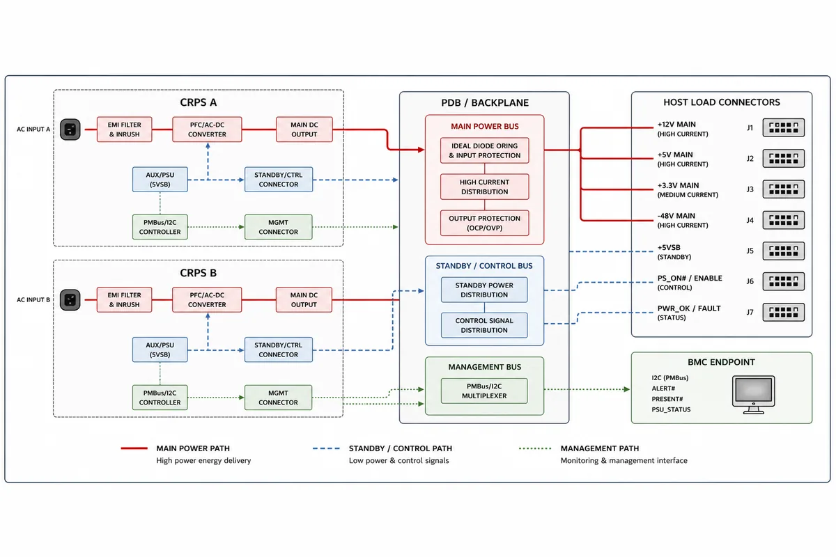
The powered stage must use an authorized host or a suitable controlled fixture. Its scope should come from the agreed acceptance schedule and the supplier’s operating instructions. Depending on the assembly and intended use, observations may include standby availability, enable response, output behavior, module-presence indication, power-good signaling, management communication, current sharing, alarms, and thermal behavior under the specified load states.
If 1+1 continuity or live replacement is part of the purchase requirement, test evidence should cover the defined degraded state. Removing a module under load is appropriate only when the exact assembly supports hot swap, the surviving path has adequate documented capacity, the procedure is authorized, and the test environment can contain the consequences of a fault. Successful insertion alone does not prove that current transfer, isolation, management, or restored redundancy behaves as required.
Acceptance criteria should identify the measurement point, condition, instrument or host indication, permitted result, and disposition for failure. Avoid inventing universal voltage, current-sharing, temperature, or timing tolerances; use the limits documented for the quoted module, board, host, and operating state.
The backplane is orderable when its noun stays stable
A well-defined CRPS redundant power backplane remains the same object through the RFQ, supplier quotation, drawing review, purchase order, receiving inspection, and spare record. Its identity includes more than the PCB: it includes the revision-controlled module interface, cage relationship, host outputs, control responsibilities, operating envelope, evidence package, and declared exclusions.
That continuity is the practical acceptance test for the commercial specification. If the quoted “backplane” changes silently from a populated PDB to a bare adapter, or if an approved revision becomes an unspecified equivalent, the purchase boundary has failed before the hardware is powered. If the same controlled assembly and its supporting evidence survive every handoff, price, compatibility, integration work, and future replacement can be evaluated against one unambiguous configuration.