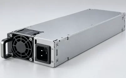
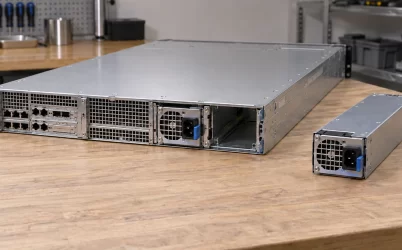
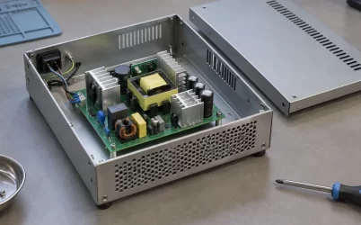
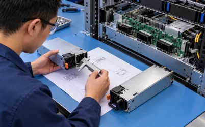
A server PSU’s gold fingers are the plated contact pads that meet the chassis’s connector when a removable module slides home. The gold surface helps keep that separable electrical interface stable through exposure and repeated mating; it does not make an undersized, misaligned, dirty, or overloaded connection safe. For a replacement module, the useful question is not simply whether the pads look gold. It is whether the complete PSU-and-receptacle contact system has the geometry, materials, current capacity, insertion durability, and thermal performance required by that server.
Some server supplies use a card-edge interface with visible fingers; others use different blind-mate connector constructions. The discussion below concerns the former and the related plated-contact principles, not a universal description of every server PSU. It explains why a thin surface finish matters, how the mating half changes the result, and what the technician should infer when a contact looks damaged.
The gold is a contact surface, not the bulk conductor
A gold finger is generally a plated region on a printed-circuit-board edge, not a piece of solid gold. Current travels through a larger path: the pad’s conductive structure, the board copper and its connections, the contact interface, the spring element of the receptacle, and the PDB or other downstream distribution path. A finish can protect the point where the two parts separate, but it cannot increase the cross-sectional area of every conductor in that chain. A bright pad is therefore no proof of a particular ampere rating.
Gold is useful at a separable interface because its surface resists formation of insulating oxide under ordinary conditions. The mating contact still needs adequate spring force and a designed wipe to establish repeatable metal-to-metal contact. The underlying material and any barrier layer, the plating method and thickness, and the exposed contact area all belong to the connector design. Thin finishes intended for limited mating duty should not be equated with finishes qualified for repeated insertion. None of those details can be established reliably from color alone.
Selective plating is common in connector engineering: material is concentrated at the actual mating zone instead of being applied indiscriminately to every portion of a terminal. That distinction matters when visually inspecting a module. A gold-colored finger at the board edge does not imply that the entire current path, solder joint, or mating socket uses the same metal. Likewise, a different visible finish elsewhere on the board is not itself a defect. The specification for the exact connector pair, rather than an impression from a photograph, defines what the intended contact surface should be.
The receptacle completes the server PSU connector
On insertion, the board edge or plug follows the chassis guides toward a fixed mating connector. A spring contact in that receptacle deflects and presses against the plated region. Its shape establishes where contact occurs, the force at that point, and the length of wipe before the module reaches its seated position. If the module is stopped short by a bent rail, damaged latch, or mispositioned PDB, the apparent connection may have less overlap and less stable pressure than intended. Gold plating cannot compensate for missing engagement.
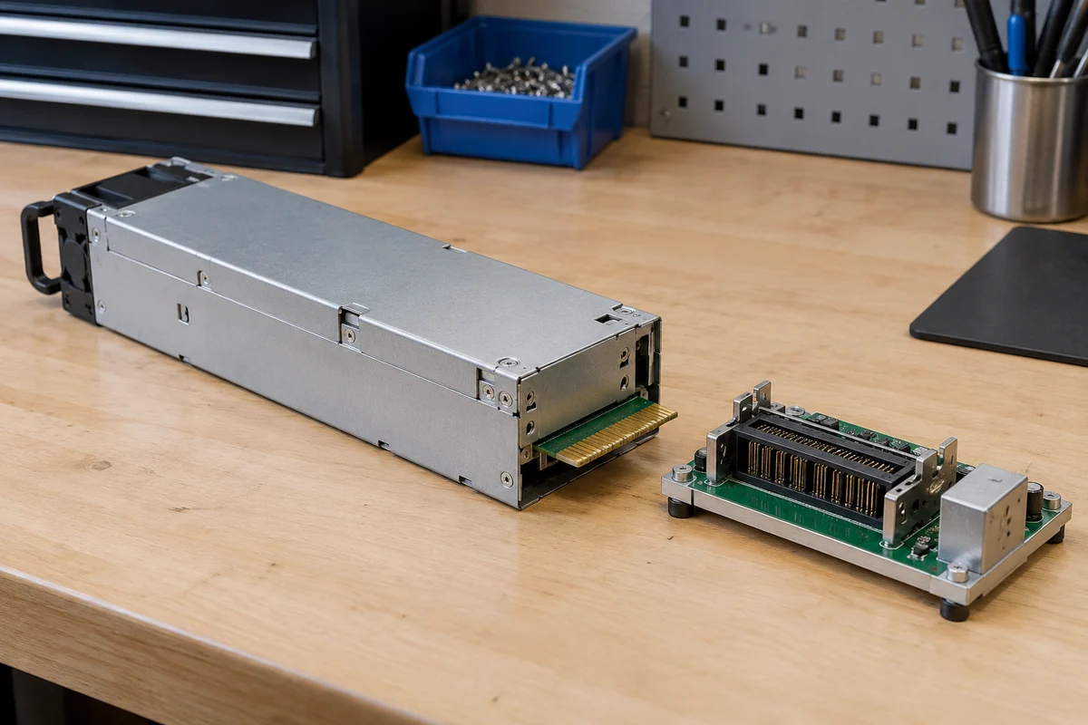
Contact wipe is the relative sliding distance of the mating surfaces. In a properly designed interface it can disturb light surface films and place the final contact region at a controlled location. Samtec’s explanation of contact wipe describes that interaction and why plating at the contact point helps reduce corrosion and maintain a low-resistance interface. It is connector-design guidance, not evidence that an unidentified PSU has a particular wipe length or service life. That requires the module’s and mating connector’s own documentation.
Blind mating also introduces a tolerance stack. The PSU case, guide rails, PCB edge, PDB mount, connector housing, and latch all contribute to alignment. A replacement cartridge that resembles the original can place its fingers differently relative to the host socket. Forceful insertion may scrape plating or deform a spring rather than correct the mismatch. Mechanical keying and an approved part number are consequently more meaningful than similar-looking gold pads. If exact signal assignments are needed, the site’s server PSU pinout discussion explains why the module and PDB must be identified together; it does not provide a universal pin map.
Why a little resistance can make a hot contact
Large-output server modules often distribute current across several parallel power and return contacts. Sharing is not automatically equal. A higher-resistance finger will generally carry less current while neighboring parallel contacts may carry more, although the exact redistribution depends on the real circuit topology. The PDB’s copper, connector termination, and return path affect the result. A total-output measurement at the PSU cannot reveal a local hot spot at a single mating point.
Resistive heating at one contact follows P = I²R. For illustration only, a contact carrying 20 A through 1 milliohm of effective interface resistance dissipates 0.4 W at that interface. If resistance in this hypothetical example rises to 5 milliohms at the same current, heating becomes 2 W. These are arithmetic examples, not measured values, safe limits, or specifications for a Powernexu or other server module. The heat is concentrated in a small region surrounded by insulating housing and adjacent contacts, so the temperature rise depends on geometry, airflow, neighboring currents, and thermal conduction.
Voltage drop follows the same local resistance. At 20 A, 5 milliohms would produce a 0.1 V drop in that hypothetical path. A small drop may be invisible in a coarse system-level telemetry reading yet still accompany meaningful contact heating. On a connector with multiple return fingers, a deteriorating return path deserves as much attention as a positive output finger. The electrical design must consider the whole mating pair under the actual input, output load, airflow, and fault conditions specified for that platform.
One discolored contact is therefore not evidence that every finger carried too much current. It can point to a local problem: incomplete seating, reduced spring force, contamination, plating wear, connector damage, a board or solder termination issue, or an abnormal current path. Visual evidence alone may not separate those causes. The important practical boundary is that a visibly heated or deformed connector should not be treated as cosmetically acceptable just because the PSU still powers the server.
What gold resists—and what it cannot repair
Oxidation resistance is the principal reason to place gold at many low-level separable contacts, but real server connector reliability involves more than atmospheric chemistry. Dust, liquids, cleaning residues, and handling contamination can block or disturb a contact. Repeated mating can wear a finish; fretting from very small movements can generate debris or degrade the interface. A rigidly mounted, well-guided, fully seated module behaves differently from a cartridge that vibrates or rocks in a damaged bay.
Contact material on the other side matters as well. Plating a PSU’s board edge cannot by itself upgrade the receptacle. Mixing contact finishes contrary to the connector manufacturer’s specified mating system can change wear and corrosion behavior. Do not assume that pairing any gold-looking edge with any available socket delivers the benefits associated with a designed gold-to-gold contact pair. Connector makers distinguish the mating surface, its underplating, spring material, and the conditions under which they tested it.
Gold is not a coating to be renewed with an abrasive pad during ordinary service. Scraping a damaged finger may remove more finish and leave a less controlled surface, while probing a live connector creates an additional hazard. Follow the platform’s power-isolation and service instructions. Where authorized service documentation permits cleaning, use its specified method and materials; otherwise replace the affected approved part or escalate the assembly for qualified inspection. A contact that has overheated enough to deform its housing may have damaged the fixed mate as well as the removable module.
Hot swapping asks more of the interface than repeated insertion
A PSU with gold fingers is not automatically hot-swappable. Live module replacement is a system capability involving the host’s supported configuration, source isolation, control sequencing, connector design, and the ability of remaining supplies to carry the load. The contact finish is only one part of that mechanism. A connector can be rated for many ordinary mating cycles yet not be designed to break load current during withdrawal. Do not infer a live-service permission from plating or from the presence of a handle.
In an approved hot-plug arrangement, different contact lengths or locations may support an intended order of engagement for power, return, presence, or control functions. The actual sequence belongs to the specific platform interface specification. It would be unsafe to assume which finger makes first merely from a photograph. If the host expects a presence signal, current-sharing response, or controlled output transfer, contact timing and firmware behavior can matter as much as the physical current pads. A substitute with superficially similar fingers may fit and still violate those expectations.
Routine replacement also has a mechanical count. A service organization that repeatedly removes a module for diagnosis consumes mating cycles in both the removable and fixed halves. The qualified cycle rating, if published, applies to the tested connector configuration and conditions, not to every variant with the same color plating. Dusty or high-vibration service may present a different risk from a clean laboratory cycle test. For recurring contact faults, investigate bay alignment, latching, contamination, and the fixed connector instead of treating another cartridge as a permanent cure.
A damaged finger can reveal a bay problem
Suppose a rack server repeatedly reports a PSU fault shortly after a module has been changed. The removed unit shows a darkened power finger. Replacing it with a third cartridge may bring the machine back temporarily, but the fixed receptacle may have lost spring force or been displaced. Every insertion then places a healthy module against the same poor contact. The failure may appear to follow the PSU even though the persistent defect belongs to the bay.
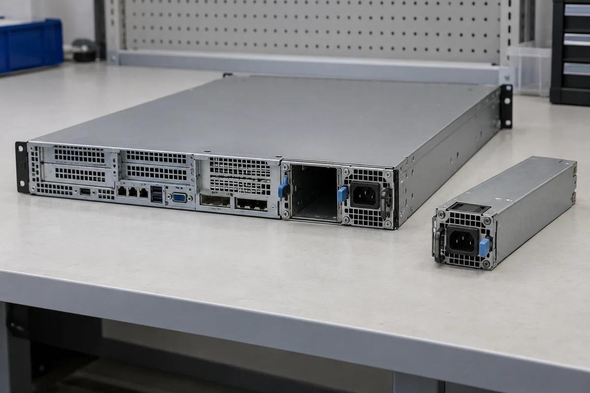
Look for an asymmetry that connects the symptom to the hardware: one bay rather than both, one localized contact rather than uniform wear, a latch that does not close fully, or a recurrent thermal mark in the same socket position. A rising contact resistance can manifest as intermittent dropout, voltage loss, localized heating, or a fault entry, but each symptom can have other causes. The host’s service manual and connector acceptance guidance determine whether the PDB, receptacle, module, or related assembly must be replaced together. Do not substitute a guessed cleaning or bending procedure for that guidance.
This is why spare planning cannot end at the cartridge. If the fixed connector is an integral part of a PDB, the repair may require access to that board, a supported replacement assembly, and enough downtime to isolate and service the chassis. Keeping only removable PSUs in inventory helps with module failures but may not resolve a worn mating interface. The equipment owner should know which half is field-replaceable before a contact fault occurs.
The finish matters most when the mating system is correct
Gold-plated server PSU fingers can help maintain a stable separable connection, especially where exposure and repeated mating would challenge a less suitable surface. Their benefit is real but conditional. The host connector must press on the intended region with the designed force and wipe, the module must seat at the correct datum, and every current-bearing element must remain within its documented electrical and thermal limits. A bright plating color establishes none of those conditions by itself.