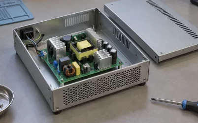
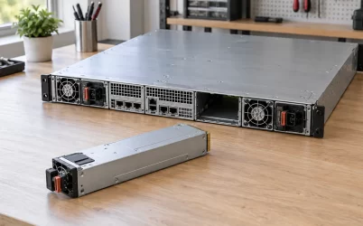
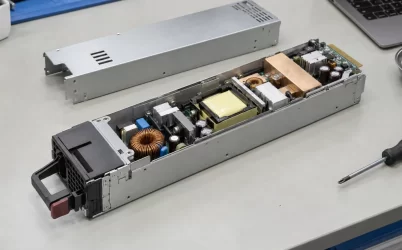
G1231-1600WNA appears in Powernexu’s catalog as a 1600 W, 1U power distribution board, but its published fields need careful interpretation. Gospower, the maker associated with the G1231 family, identifies G1231 as a 1U, 1+1 PDB backplane intended to work with 185 mm CRPS modules. A PDB receives and distributes power from installed modules; it is not itself the AC-input conversion module. The public manufacturer page does not establish the electrical specification of the exact -1600WNA suffix. Anyone ordering this assembly should therefore verify the suffix, its mating PSU list, and its output connector map before treating the catalog’s AC-input and rail-current entries as controlled PDB specifications.
The G1231 family is a backplane between CRPS modules and the host
A server power assembly has distinct jobs. The CRPS modules convert an approved input into regulated DC power. A distribution board mates with those modules and routes their outputs into the server’s harnesses, motherboard, drives, and auxiliary circuits. The host may also rely on the board for sensing, control, protection, or combining functions, depending on the particular design. The board’s mechanical position and interface therefore matter even if the electrical ratings of the installed supplies are known.
Gospower’s G1231 family page calls the product a PDB backplane in a 1U 1+1 configuration. It says the board can be combined with 185 mm CRPS supplies to form a redundant power system and can provide standard ATX power output or customized output ports. Those are family-level statements. The same page includes promotional highlights whose figures and application labels are not sufficiently tied to the suffix in this article to serve as its rating table. No publicly readable, revision-controlled G1231-1600WNA drawing or suffix-specific pin map appeared in the manufacturer page reviewed for this article.
The Powernexu G1231-1600WNA listing describes a 1600 W, 1U PDB and gives approximate dimensions of 226 × 156 × 41.5 mm. It also lists 90–264 V as a minimum-to-maximum input and names +12 V, +5 V, +3.3 V, -12 V, and standby output currents. Those fields resemble a combined supply-system description, but they do not say which voltage is presented at the board’s PSU-side interface or how each rail is generated. A PDB that mates to an AC-input CRPS module is normally downstream of the module’s AC conversion stage. The catalog data should not be interpreted as evidence that AC mains enters the bare backplane. That distinction changes both safety design and procurement.
Read the 1600 W figure as a system claim until the interface is documented
The suffix and headline power identify a 1600 W class offering in the available catalog, but they do not establish 1600 W of independently deliverable power on every output. A multi-rail assembly has a combined limit as well as current limits for individual branches. If several outputs are used at once, their allowed combinations need a power table or controlled drawing. Adding the maximum current of every listed rail after multiplying by its nominal voltage could overstate the assembly’s simultaneous capacity. Some rails may derive from DC-DC converters on the PDB, while others may be passed through from the CRPS; the public suffix data does not resolve that architecture.
For example, the catalog’s +12 V / 132 A entry would correspond to 1584 W if that current were continuous at exactly 12 V. That arithmetic is useful for spotting how close the rail entry sits to a 1600 W headline. It does not prove the load is permitted continuously, define the voltage tolerance, or show what remains for the other outputs. The catalog’s +5 V / 25 A and +3.3 V / 25 A entries likewise cannot simply be added to the 12 V product as independent simultaneous maxima. The engineering question is the allowed load matrix for this exact revision, including the standby branch, connectors, copper, contacts, thermal conditions, and the installed CRPS pair.
Input dependence belongs in that matrix too. A CRPS module’s available output can vary with its AC feed, although the particular curve depends on the module selected. If the host is intended to keep running after one PSU is removed or one feed fails, the surviving module’s rating at the surviving feed must carry the required host load. Two 1600 W labels do not create a 3200 W protected load in a 1+1 arrangement. The board must also be rated for the current and transition behavior it sees in the failure case. The exact G1231-1600WNA public listing does not provide enough information to establish that complete scenario.
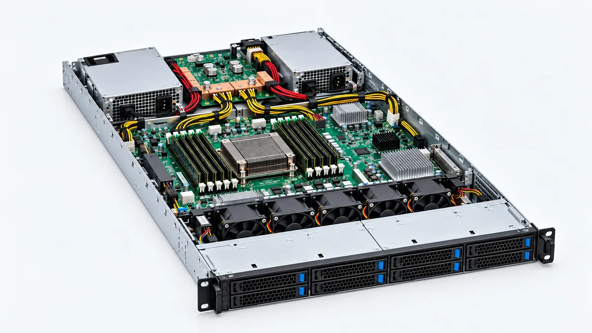
The diagram separates the two conversion modules from the central backplane and the downstream loads. It is an interface concept, not a wiring diagram or a verified pinout for G1231-1600WNA. That separation is especially useful when a seller describes a PDB with an AC input field: the AC connection may belong to the modules in the assembly rather than the bare PDB. Ask for a bill of materials that names the board and each compatible module separately.
Mechanical fit starts at the mating plane, not the overall dimensions
A 1U designation limits the chassis height class, but it does not define the board outline, screw locations, connector placement, or insertion direction. The Powernexu page’s 226 × 156 × 41.5 mm entry and the Gospower family page’s roughly 225 × 153 × 41.5 mm highlight are close in envelope. They are not substitutes for a controlled assembly drawing. The small length and width difference could reflect rounding, different reference planes, a revision, or a different configuration; the public pages do not identify which. Neither set of numbers locates the PSU contact system or confirms that the suffix fits a particular host.
In a 1U chassis, the PDB commonly sits close to the rear PSU bays. The guided modules must reach the board’s mating contacts at the designed depth. A few millimeters of connector displacement can prevent engagement or change how the latch seats, while a different mounting pattern can place the board against a fan or cable path. A board may have the right outer dimensions yet put an ATX output connector where the motherboard cannot accept the harness. Compare the whole assembly: board outline, mounting holes, insulating supports, PSU insertion axis, retention hardware, connector orientation, rear service clearance, and cable bend radius.
The manufacturer states that the G1231 family can work with 185 mm CRPS supplies. That does not mean every 185 mm CRPS unit has the correct electrical edge contacts, control signals, airflow option, or mechanical keying. CRPS describes a form and interface family, while host suppliers frequently qualify exact part numbers. Treat a 185 mm length as one necessary mechanical check, not an interchangeability certificate. A host service manual or approved-vendor list carries more weight for a replacement than a generic dimension match.
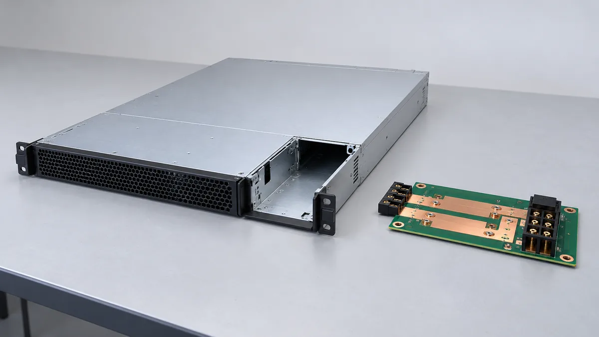
The plan-view illustration shows why the PSU mating edge, mounting points, and host connector zone must be evaluated together. It intentionally omits real G1231 connector geometry because that geometry has not been verified from a manufacturer drawing.
Output rails must be traced to their source and connector
The available catalog entry names several nominal output rails. That list is a starting point for questions, not a host wiring instruction. One rail may pass through from the PSU, another may be generated on the board, and another may be available only under a specified control state. Even when two assemblies use the same rail names, their connector pin positions, returns, remote sense, signaling, and permissible loads may differ. A mating plug does not prove an electrical match. Applying power with an assumed pinout could damage the board or host.
Trace the power path from the selected CRPS module’s published output contacts into the PDB, then from each PDB output connector to its actual load. Record which rails are present in standby, which turn on with a system command, and which depend on the main output. For the listed -12 V branch, establish whether the host uses it at all and how much current it draws; a legacy rail name can be retained in a catalog even where the host’s actual demand is small or absent. For +5 V and +3.3 V, obtain their combined loading rule if both originate from onboard converters or share a common upstream limit.
Return paths deserve the same attention as positive rails. At high current, the number and placement of return contacts determine current distribution and heating. Control and sense signals must not be confused with power pins simply because they lie on the same edge connector. If a board has output protection, ORing, current sharing, or management communication, the actual revision documentation should identify the behavior. Gospower’s general statement that the family supports hot swap describes a system capability; it does not publish the insertion sequence, connector pin map, or service procedure for this exact suffix.
Redundancy depends on the complete pair and the failure path
The G1231 family page describes a 1+1 configuration. That term usually means two modules are present so a single surviving module can support the intended load, provided each module and the shared distribution path are rated for that condition. The PDB itself is a shared component and may remain a single failure domain. Whether the board includes isolation devices or fault containment needs documentation. A board labeled 1+1 should not be represented as two independent power paths all the way to the motherboard.
Consider a server drawing 1100 W of DC output under its defined worst operational load. If each selected module is actually rated for at least that output under the available feed and ambient conditions, a nominal 1600 W module could leave capacity for a single-module failure. That simple comparison says nothing about the PDB’s combined-load restrictions, branch-current ceilings, transient behavior, or connector temperature. If one module derates on the site’s lower-voltage feed, the remaining capacity could fall below the host demand. This is an illustrative load, not a measured G1231 deployment.
Resolve the catalog conflict at the orderable-part boundary
The public record supports a clear family classification: G1231 is a 1U 1+1 PDB intended to mate with 185 mm CRPS modules. It does not resolve the exact suffix’s input definition, rail-generation scheme, current-combination rules, pinout, or revision-dependent dimensions. The Powernexu page gives a useful commercial identity for G1231-1600WNA, but its AC input field should be reconciled with the actual board and PSU documents before a purchase specification adopts it. A bare PDB is not automatically an AC-input supply.
The fastest useful supplier response is a compact document set for the precise orderable part: a controlled G1231-1600WNA datasheet or drawing with revision, a complete assembly photo and label, a compatible-PSU list, the PSU-side and host-side connector definitions, a combined-load table, and the intended 1+1 operating conditions. Include the server chassis and motherboard part numbers in the inquiry so the supplier can identify a host-specific variant if one exists. If the offer bundles CRPS modules with the PDB, ask for every module’s full model and input-dependent rating separately.
Once those documents agree, the decision becomes concrete. The board must physically seat in the chassis, accept the approved modules, route each required rail to the right host contacts, and carry the load after the defined single failure. If the supplier cannot link the -1600WNA suffix to a controlled board drawing, the published figures remain catalog clues rather than a safe basis for substitution. That is the practical distinction behind the G1231 search result: this model is principally a distribution interface in a redundant server power assembly, and its success depends on the specific modules and host on either side.