A “2U 24VDC power supply” may describe two very different machines. In one, 24 V DC enters a 2U rack computer and a DC-DC supply creates the lower-voltage rails its motherboard needs. In the other, AC enters a 2U rack power system and 24 V DC leaves through protected output circuits to equipment elsewhere. The same rack-height and voltage words appear in both listings, but the input connector, output wiring, conversion stages, and loads are not interchangeable. Before comparing wattage or price, locate the 24 V label on the power path.
First find which side of the converter carries 24 V
“2U” describes the rack space occupied by the host or power shelf, not a universal electrical interface. One rack unit is a mounting increment; a 2U product occupies roughly twice that vertical space, but it may be a computer, a DC-UPS, or a rectifier shelf. The phrase “24VDC” is equally incomplete without “input” or “output.” A photograph of the front panel may show neither. A product drawing, rear-panel view, and the electrical specification usually resolve the question more quickly than a search-result title.
For a DC-input computer, the upstream source might be an industrial 24 V distribution system. The computer’s internal converter accepts that DC feed and produces rails for processors, drives, fans, and control logic. For a 24 V output shelf, the upstream source is commonly AC; rectifiers create a DC bus and output distribution sends it to external loads. A DC-UPS may add batteries and switching that keep the bus energized when AC disappears. Neither arrangement follows automatically from a 2U enclosure.
Steatite, for example, lists a specific 2U rackmount PC with an optional 24 V DC input PSU. By contrast, SEI’s official 2U 24 V DC-UPS description describes an AC-fed rack system with 24 V output ports and internal batteries. These are examples of two legitimate uses of the phrase, not specifications for a generic 2U supply and not claims about Powernexu products. A 24 V input option for one computer does not imply that the computer supplies 24 V to its external peripherals. A 24 V output shelf does not imply it can replace that computer’s internal PSU.
When 24 V enters the 2U computer
The useful electrical drawing begins at the DC source, passes through the rack’s feed protection and input wiring, enters the computer’s DC-DC converter, and ends at the specified computer rails. Depending on the motherboard and converter, those rails may include 12 V and lower logic supplies. A single 24 V input does not reveal the output connector arrangement. A computer designed around ATX-related rails needs the exact supported distribution and control interface; a bare 24 V line is not a substitute for its internal supply.
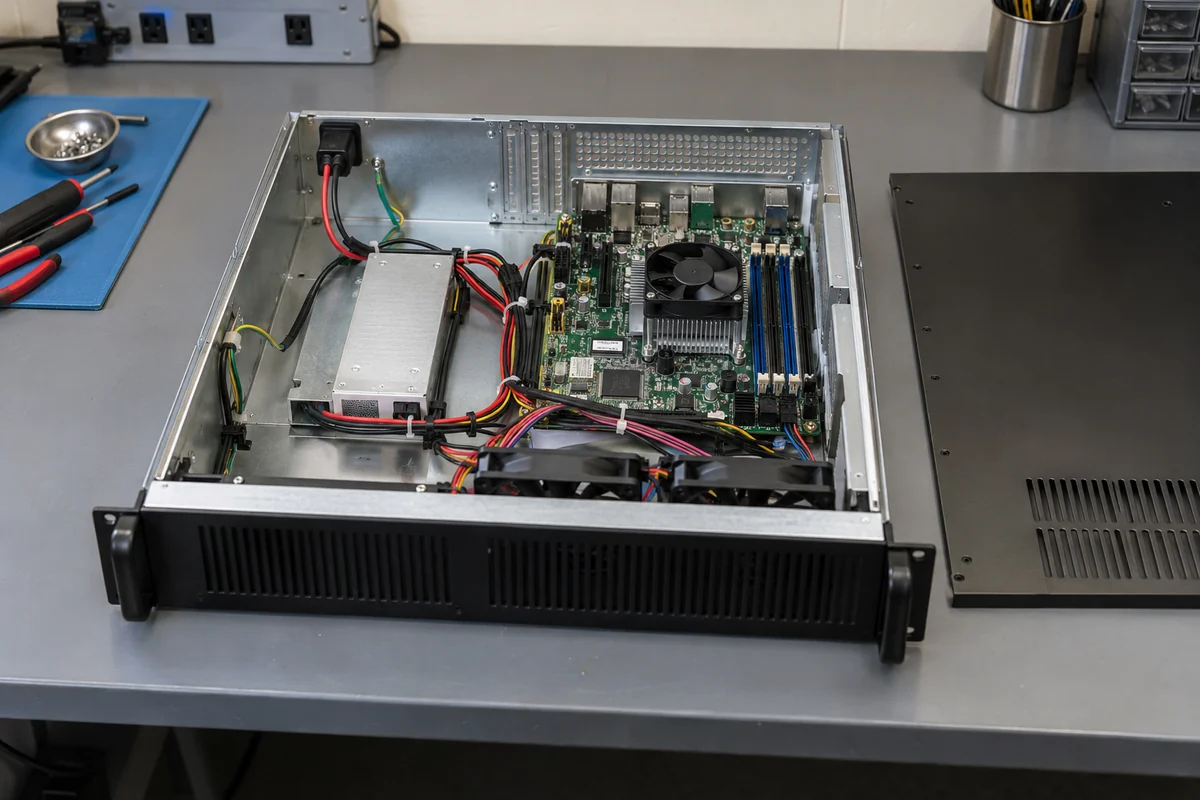
Input current becomes important because a low-voltage feed carries substantial current at server-like powers. Consider a hypothetical computer consuming 480 W at the converter output while the converter operates at 90% efficiency at that point. Input power is about 533 W. At a nominal 24 V feed the input current is about 22.2 A. If the actual voltage at the PSU terminals falls to 20 V while the load and efficiency remain approximately the same, current rises to about 26.7 A. These are illustrative calculations, not a rating for a named product. Actual limits must come from its specified input range, efficiency curve, peak behavior, and connector temperature limits.
The distinction between nominal voltage and terminal voltage matters on a long rack feed. Cable resistance, connector contact resistance, distribution fuses, and a transient load all contribute voltage drop. If the upstream battery or plant is near the low end of its range, the converter must still receive enough voltage at its own input terminals, not merely at the distribution panel. If a 24 V-source circuit can deliver the power in steady state but trips on startup, the issue may be inrush, source current limiting, or protection coordination rather than insufficient continuous wattage.
Polarity and return routing are another DC-input concern. A source described as “24 V” can use different grounding and isolation practices depending on the installation. The converter may expect a particular positive and return orientation, a protected input connector, or a separated chassis bond. The correct answer is in the specific computer and PSU documentation. One must not transfer the wiring convention from a telecom plant, vehicle system, or another manufacturer’s rack computer merely because the printed voltage matches.
When 24 V leaves a rack power shelf
Now reverse the direction. A 2U 24 V output system accepts an energy source—often AC—converts it, and distributes a DC bus to external equipment. The output side may include breakers or fused ports, supervision, battery charging, and a low-voltage disconnect. Those functions belong to the entire rack power system, not necessarily to one replaceable rectifier module. A buyer who orders only a converter cartridge when the project requires a complete shelf may be missing the distribution and control hardware.
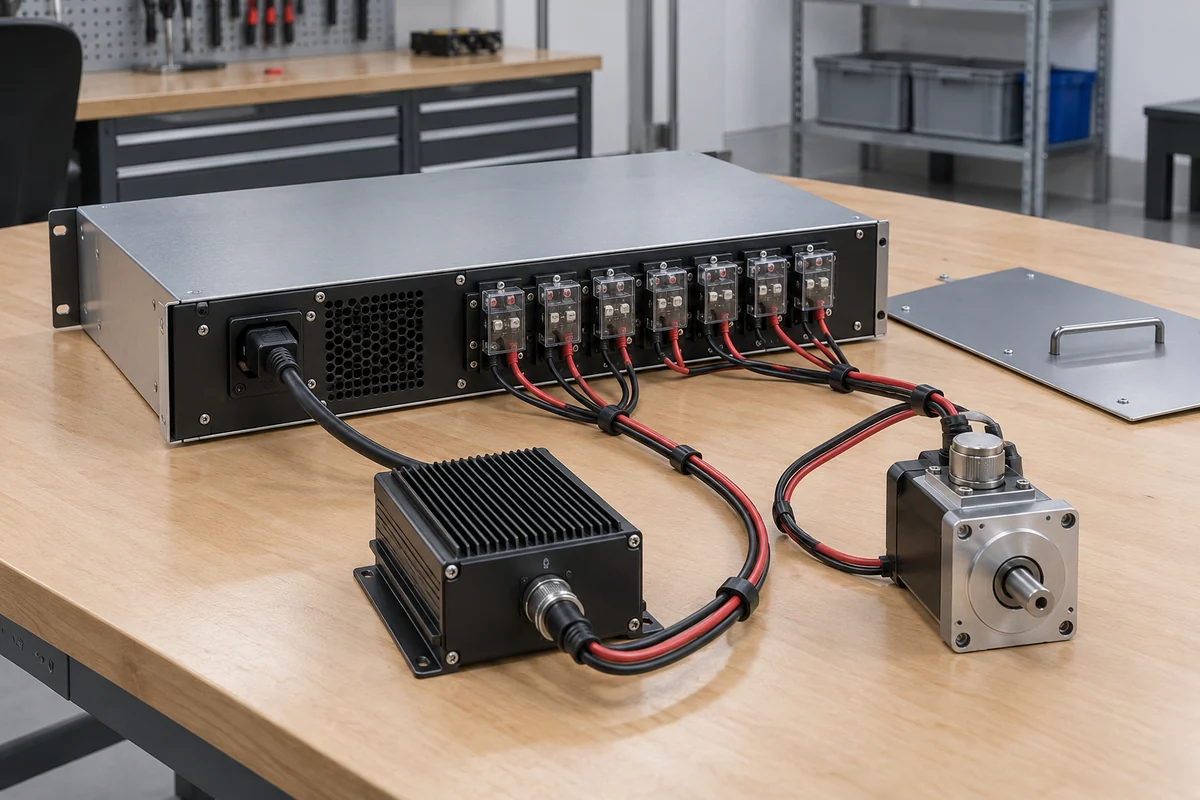
SEI’s particular 2U DC-UPS is a useful concrete example: its published product description identifies internal batteries and individually protected output ports. Its installation manual distinguishes the AC connection from rear 24 V output terminals. This is a DC plant in a compact enclosure, not a multi-rail ATX supply for a motherboard. Another manufacturer’s 2U rectifier shelf may have different port counts, battery functions, and service arrangements. The architectural point is that the 24 V bus is intended to serve a set of loads, so branch protection and the return path matter as much as the converter rating.
Suppose a rack output bus is specified for a hypothetical 600 W of usable 24 V load. At exactly 24 V, that represents 25 A distributed among branches. A 25 A bus does not mean that every branch terminal may carry 25 A. Branch fuse or breaker ratings, conductor size, terminal ratings, and the system’s total power limit apply independently. Nor does a rectifier’s wattage tell the whole story if some available power is reserved for battery recharge after an outage. Product-specific ratings determine how much can be delivered continuously to external loads in each state.
Output voltage may also be regulated to a value above a nominal “24 V” label when charging batteries, and it may decline during discharge. The load’s permissible input range must be compared with the entire bus operating envelope, including battery and transition states, rather than only with nominal voltage. If some attached devices require regulated 12 V or 5 V, a separate downstream DC-DC stage may be present. The presence of such secondary outputs in a particular shelf should never be presumed from the words “2U 24VDC.”
Redundancy here means something different from two computer PSUs. Parallel rectifier modules may preserve conversion capacity after a module fails, provided the remaining modules can support the load and charging policy. A battery may bridge an upstream AC interruption but does not automatically protect against every DC-bus short. Separate fused branches can confine a load fault, but their selectivity depends on the actual protection design. These are separate layers of resilience; the one phrase “redundant 24 V supply” does not establish all of them.
Why the two 24 V paths do not substitute for each other
A DC-input computer PSU and a 24 V-output distribution shelf differ at their most basic terminals. The first expects a 24 V source and sends several specified rails into one host. The second creates a 24 V source for many possible loads. Connecting the output of a rack shelf to a DC-input computer may be a valid system design only if the shelf’s voltage envelope, branch current, transient capability, protection, connector, return, and grounding match the computer’s documented requirements. It is not a drop-in replacement for the computer’s internal converter.
The direction also changes what the wattage number measures. On a DC-input computer, a PSU’s advertised output wattage concerns power supplied to computer rails under defined input and cooling conditions; its source must provide that output plus conversion loss. On an output shelf, the published system capacity may be a total bus figure, while each branch has a lower protection rating and available load power may vary with rectifier population or battery charging. Comparing two “600 W, 2U, 24 V” listings without those definitions can put a component against a complete system.
A short schematic often clarifies a project faster than a catalog filter. Draw the source on the left, the conversion and storage functions in the middle, and the protected load circuits on the right. Mark each 24 V label at the point it actually describes. If the rack computer is the load, identify the conversion into its lower-voltage rails. If 24 V is delivered to field devices, show the branch distribution and return. If both appear in one installation, the 24 V output system may feed the 24 V-input computer, with the host’s internal DC-DC converter still required. That series arrangement is not a contradiction; it is two different jobs in the same power chain.
The voltage label is only the beginning of the electrical match
A 24 V-input converter has a permissible input range, not merely a nominal point. A 24 V-output system likewise has regulation limits and transient behavior. To connect them, compare the source’s minimum and maximum terminal voltage with the load’s accepted range during steady operation, startup, charging, discharge, and changeover. There may be a moment when a source remains technically “24 V nominal” but falls below a computer’s undervoltage threshold during a load step. The opposite problem is also possible if a charging bus rises above the equipment’s permissible input maximum.
Current capability has a time dimension. The rack shelf may support a large continuous current but limit a short startup surge. The computer may draw a brief input pulse while charging internal capacitance. Cable and connector ratings need to tolerate both normal heating and the selected protective device’s clearing behavior. For a fault, the question is not simply whether the source has enough watts; it is whether a branch fault opens the intended branch without collapsing the common bus. That requires the actual source, fuse, breaker, and converter characteristics, not a generic “24VDC” search result.
Cooling can also expose a false equivalence. A DC-DC converter inside a computer depends on that chassis’s intake and fan layout. A standalone shelf has its own inlet and outlet conditions and may need clearance for battery compartments or rectifier service. The fact that both fit below a 2U height line does not allow either to operate with blocked vents or with a different thermal load profile. Temperature limits and derating curves apply at the local air inlet specified by each product, not simply at the room thermostat.
Read the next specification in the right direction
For a rack computer, the useful specification begins “24 V DC input” and continues with the permissible range, input current, inrush behavior, output rails, connectors, and host compatibility. For a rack distribution system, it begins with its upstream input and “24 V DC output,” then defines total usable bus power, branch limits, voltage operating range, batteries or rectifier population where fitted, and load connections. Neither description can be compressed safely into “2U 24VDC power supply.”
The practical result is simple. If the intended load is a motherboard inside a 2U computer, identify a supported DC-input conversion option for that exact host. If the intended loads are external 24 V devices, identify a rack system with the required output distribution and source-continuity behavior. If one must feed the other, compare their complete voltage and current envelopes at the connecting terminals. The search phrase names a rack height and a voltage; the electrical direction defines the product.