A CRPS power distribution board with cage can provide a starting point for adding removable power modules to an existing computer. Whether it justifies keeping the chassis depends on what the conversion displaces.
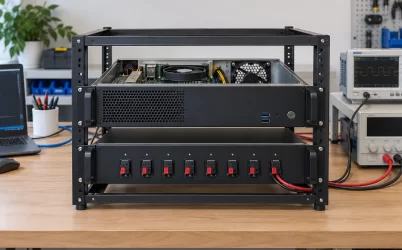
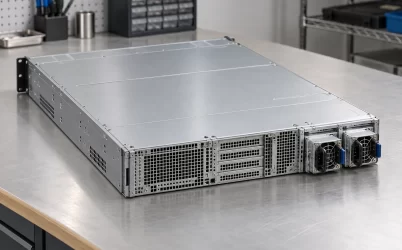
Consider a hypothetical storage host with a fixed power supply, a removable rear mounting plate, and drive carriers that must remain accessible. Its owner wants continued operation during an approved PSU replacement. Two routes deserve comparison: integrate a documented cage-and-PDB assembly into the existing enclosure, or move the retained computing and storage hardware into a chassis designed for the required removable-power arrangement.
The cage purchase serves that larger choice. An assembly can accept its specified modules yet require changes that erase the practical advantage of retaining the enclosure. This example examines those changes without claiming a verified retrofit for any named host.
What is worth retaining in the existing storage host?
The original chassis has value beyond its purchase price. Its drive carriers, storage-backplane position, motherboard mounting, rack attachments, and external connections already serve a particular installation. Keeping those relationships can reduce the scope of a power conversion. Losing them while preserving the outer shell produces a different project.
For this hypothetical host, assume the drive arrangement and installed motherboard must remain. The rear mounting plate may be replaced, but the chassis frame and storage cage must stay intact. These are stipulated project constraints, not features attributed to a commercial server. They establish where a cage installation may change the enclosure and where it must accommodate existing hardware.
A removable rear plate creates a possible boundary for localized metalwork. A replacement plate could carry a suitable power assembly while leaving the main enclosure unchanged, provided the attachment and support design permits it. That possibility differs materially from cutting a structural rear member or moving the storage cage. Neither outcome follows from the presence of an empty volume near the old supply.
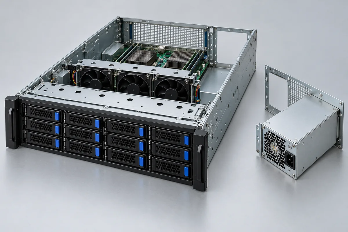
Some retained features may have little remaining value. A fixed supply’s cable clips may be poorly placed for the new harness. Its ventilation opening may not suit the proposed assembly. Conversely, relocating a drive backplane could disturb both storage wiring and cooling. Distinguish disposable provisions from the relationships that make retaining this particular chassis worthwhile.
This distinction also limits compromise. If preserving the enclosure requires deleting a needed drive position, the retrofit no longer delivers the original storage configuration. Compare that reduced configuration explicitly rather than treating lost functionality as an incidental installation detail.
CPB01 establishes a candidate assembly, not a host conversion
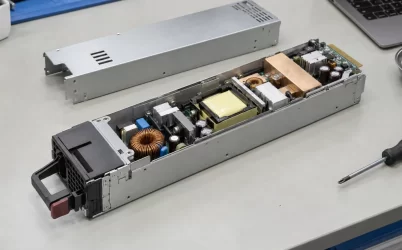
SilverStone’s CPB01 manufacturer product page identifies SST-CPB01 as a CRPS power distribution board with cage. It describes accommodation for two vertically installed modules and names GM2000C-TFU and GM2400C-TFU. These statements identify a concrete candidate and supported module references; they do not establish installation in the hypothetical storage host.
The published cage dimensions are useful starting evidence. SilverStone lists 169.8 mm width, 45.2 mm height, and 353 mm depth including the bracket. It also lists 153.8 mm width with the same height and depth excluding the bracket. Preserve those separate measurement boundaries. The narrower entry does not establish permission to omit a bracket required by the intended installation.
Likewise, the manufacturer’s vertical-installation wording should be interpreted through its assembly drawings. Rotating a product photograph to suit a convenient chassis opening does not establish a supported mounting orientation. For the retrofit comparison, the important question is whether the documented arrangement can occupy the permitted rear region while retaining the host’s mandatory hardware.
SilverStone expressly states that CPB01 includes the cage, distribution board, and cables, with PSUs excluded. That makes the named cartridges separate integration and purchasing items. Their applicable input, output, and cooling requirements still belong to their own documentation. No module rating or surviving-system capacity is derived here from the cage’s headline power description.
The page also tells installers to match its mounting holes to the chassis mounting positions. That instruction exposes the unresolved relationship directly: the supplied product evidence does not connect CPB01’s attachment geometry to this host. A manufacturer assembly drawing and the host’s rear-plate drawing would address that gap more effectively than another general CRPS description.
Follow the proposed cage through the host changes it creates
Start the proposed installation at the rear plate and follow its consequences inward. If a suitable replacement plate locates and supports the cage without changing the frame, the first change remains local. If the same location occupies motherboard space or blocks a required storage connection, the retrofit spreads into hardware the project intended to retain.
The cage’s depth must be considered with its host-facing connections installed. A nominal assembly envelope can fit while the output cable bend occupies the storage cable corridor. Moving that harness elsewhere may require different retention points or place it across a removable component. The relevant consequence is additional host modification, rather than a minor discrepancy between two rectangular outlines.
Support can expand the work further. A rear plate that positions the assembly may not, by itself, provide the required support for its installed mass and service forces. The applicable cage instructions and mechanical design determine the attachment arrangement. Adding an internal support is feasible only if its location preserves the motherboard, storage assembly, and their required access.
Cooling introduces another connection to retained hardware. Removing the original supply changes the enclosure’s openings and potentially its air paths. The proposed cage may also occupy space previously used by a duct or cable passage. A retrofit that requires a new fan arrangement or relocated storage hardware has moved beyond a rear-plate substitution, even if the new power assembly itself remains unchanged.
These effects can accumulate. Suppose the candidate location requires moving the drive backplane to clear output wiring. That move then requires different storage cables and changes the fan passage. The cost comparison now includes storage integration and cooling work. Calling the project a PSU conversion understates what must actually change.
Detailed connector positioning and extraction geometry belong to the specific installation design. Here they serve an earlier purpose: identifying whether retaining the enclosure still preserves its useful arrangements. A collision that can be resolved within the replaceable plate is different from one that propagates through the storage architecture.
The retained motherboard can preserve a second integration problem
Keeping the motherboard avoids one migration task, but it leaves its original power contract in place. The new assembly must supply the required rails, simultaneous loading, standby behavior, and control relationships. A cage that accepts approved CRPS cartridges closes the upstream module question without necessarily closing the downstream host question.
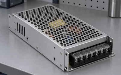
CPB01’s product page lists several host-facing voltage outputs and familiar motherboard and processor connector descriptions. Those entries make it relevant to an investigation involving a conventional motherboard power arrangement. They do not establish contact assignments, timing, or permitted loading for an unidentified motherboard. Connector appearance supplies no substitute for the two sides’ applicable interface documentation.
For the hypothetical storage host, separate the motherboard feed from the storage-backplane feed. The original fixed supply may have served both through a particular cable arrangement. Retaining the motherboard while changing the distribution hardware can require a new storage harness even when a motherboard lead appears suitable. That additional harness must be included in the retrofit’s engineering scope.
The service objective also needs host support. Continued operation during a module replacement requires adequate surviving capacity and supported replacement behavior in the assembled configuration. Two occupied bays do not establish that outcome. Powernexu’s CRPS distribution-board design discussion addresses the surrounding electrical requirements; this comparison asks whether establishing them is reasonable within the proposed chassis conversion.
Management can add work without changing the metalwork. A documented management connector on the PDB does not establish that the retained motherboard can interpret the available information or provide the desired replacement alerts. If the service requirement depends on those alerts, the missing host integration belongs beside the harness work rather than disappearing from the project estimate.
Compare two completed installations against the same storage duty
A fair comparison keeps the required drive population, computing hardware, and PSU service objective constant. The retrofit route includes the retained chassis plus its necessary changes. The alternative includes a suitable replacement chassis and the work needed to migrate the retained hardware. Comparing a cage price with a complete enclosure price would omit different obligations on each side.
| Required outcome | Retain the existing chassis | Change the chassis |
|---|---|---|
| Preserve storage capacity | Cage and wiring must leave required drive positions usable | Replacement must accommodate the required drives and backplane arrangement |
| Support removable power modules | Integrate cage mounting, support, and host interfaces | Select the documented power option for the chosen enclosure |
| Retain computing hardware | Resolve connections within the existing layout | Resolve mounting, connections, and expansion in the new layout |
| Maintain future serviceability | Support the modified host and its custom parts | Establish the replacement chassis’s applicable service and spare arrangements |
Changing chassis does not eliminate integration. The motherboard may fit a recognized mounting pattern while an expansion card, storage backplane, or front-panel connection still requires attention. A replacement enclosure should be assessed as a specific configuration, including its power option. An empty chassis advertised for redundant supplies does not establish that the necessary power assembly arrives with it.
Retrofitting can remain attractive when the existing storage arrangement is difficult to reproduce and the power changes stay localized. A supported rear plate and documented harness may preserve valuable host relationships. The advantage becomes weaker when the project must redesign internal supports, relocate storage, create new cooling provisions, and maintain custom management behavior together.
Future maintenance changes the comparison as well. A custom plate or harness needs a reproducible identity and replacement route. Otherwise, the second machine or a later repair can depend on reconstructing the first conversion. A replacement chassis may offer established spares, but their availability and applicability require confirmation rather than assumption.
No universal labor allowance or cost-saving percentage follows from these differences. Obtain project-specific estimates for the actual modifications and migration work. Count engineering that can be reused across identical hosts separately from per-machine assembly. A conversion for one legacy system and a repeatable conversion for a fleet can justify different investments.
For this host, the rear plate is the turning point
The hypothetical host remains a credible retrofit project if a documented cage installation can be carried by its replaceable rear plate, supported without altering retained hardware, and connected to the motherboard and storage assembly through an established power arrangement. Those conditions preserve the reasons for keeping the enclosure while changing its PSU service method.
The assessment shifts toward another chassis if accommodating the cage requires moving the storage backplane, sacrificing required drives, or substantially rebuilding the cooling arrangement. The original enclosure then contributes less of the installation being preserved. A replacement designed for the required removable-power option deserves comparison before committing to those changes.
The evidence presently available does not resolve the actual mounting relationship, installed output-cable envelope, or host power-and-control agreement. CPB01 is therefore an identifiable candidate, not a demonstrated retrofit. An applicable assembly drawing paired with the host layout could show that the changes remain local—or reveal the first interference that makes them spread.
That result determines the useful next purchase. A localized, documented conversion supports acquiring the assembly for the retained host. A conversion that displaces the storage relationships motivating retention supports investigating another enclosure. The practical value of the cage is how much of the existing machine it allows the project to keep.