Modern server power supplies can be highly efficient because their designers work on losses at several different points in the conversion path, not because one part “makes the PSU efficient.” Energy can be lost in the AC input rectifier, power-factor-correction stage, isolation converter, output rectifier, current-sharing or ORing devices, wiring, control electronics, and fan. A small improvement at one high-current point can be significant; a clever circuit in a low-loss point may barely move the total. The specific topology varies by product. There is no universal server PSU circuit, and a published efficiency figure belongs to one tested design and operating condition.
The input stage can improve current shape without erasing loss
An AC-input server supply first deals with line power and usually needs to produce a controlled DC bus for the isolated conversion stage. The input may include filtering, inrush control, rectification, and active power-factor correction (PFC). Active PFC shapes input current and regulates an intermediate bus. It is important not to confuse its power-factor function with conversion efficiency: a power factor near unity says that real and apparent input power are close under the stated conditions; it does not prove that little real power is dissipated inside the PSU. The switching devices, magnetic components, sensing circuits, and input rectifier all have loss.
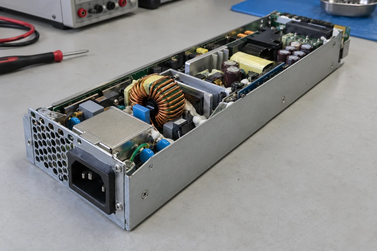
In a conventional bridge-rectified arrangement, input current flows through rectifying devices whose voltage drops become heat. A bridgeless or totem-pole PFC arrangement can avoid part of that bridge conduction path, but it adds demanding control, switching, protection, and electromagnetic-interference considerations. The point is not that every server supply should use one of those arrangements. It is that reducing a repeated input-side conduction loss is one possible route to higher efficiency when its practical penalties are acceptable. Texas Instruments’ server-power design article discusses bridgeless PFC as an evolving option, not a mandatory feature of every module.
Input voltage also changes the loss picture. Delivering the same real power at a lower AC voltage generally requires more input current, so resistive loss in a given conductor or switch path tends to rise with the square of current. At a higher input voltage, some conduction losses can fall, while switching stress and other details may change. A designer must optimize the actual supported input range, not just one preferred laboratory point. This is one reason a single attractive efficiency number cannot be treated as an invariant property of the PSU.
Inrush limiting illustrates a trade-off that a simple topology list hides. A resistor can tame startup current but would waste power if it remained in the main path during normal operation. Bypassing it after startup can reduce steady loss, although that introduces a relay or solid-state switching device with its own failure and control considerations. The best implementation depends on required input range, cycling behavior, size, and thermal environment. Efficiency is gained through a whole operating sequence, not by eliminating every protective function.
Switching losses are shaped by when voltage and current overlap
After the input stage, an isolated DC-DC converter changes the high-voltage bus into the server’s intended output voltage while providing the required isolation. A transistor that changes state while carrying substantial current and blocking substantial voltage can dissipate energy at each transition. Increasing switching frequency may shrink magnetic components, but it can multiply transition and gate-drive losses. Lower frequency can reduce some of those losses but demand larger magnetics and filtering. Power density and efficiency therefore interact; neither can simply be maximized without regard to the other.
Soft-switching topologies aim to make a transition when voltage, current, or both are relatively low. An LLC resonant converter, used in some server designs, can create favorable switching conditions over a defined range. It is not an all-load guarantee. Far from its intended operating region, circulating current, control mode, and component parasitics can change its efficiency. Other server PSUs may use a phase-shifted full bridge or another isolated converter chosen for a different power level or control objective. The benefit comes from the achieved switching behavior in that actual circuit, not from the letters in a topology name.
A concrete reference helps without creating a false rule. Toshiba’s official server PSU reference design identifies one 500 W example that combines continuous-current-mode PFC, a half-bridge LLC converter, synchronous rectification, and output ORing. Its published efficiency and dimensions describe that one design under its stated test condition. They do not imply that a different wattage, voltage, or Powernexu model has the same internals or result. What the example shows is the location of several optimization opportunities in one real conversion chain.
Magnetics are part of the same story. A transformer’s winding resistance creates copper loss, while core loss depends on material, flux swing, and frequency. An inductor may need enough current capability to avoid saturation but still have enough low-resistance copper to avoid excessive heating. Better switches alone cannot compensate for a poor magnetic design, nor can a premium core undo a badly timed switching transition. Component selection and board layout determine how the named topology actually performs.
At a low-voltage output, rectifier loss is hard to hide
A high-power, low-voltage server output carries substantial current. At a hypothetical 600 W on a 12 V output, the output current is 50 A. A rectifying path with an illustrative 0.5 V forward drop would dissipate 25 W at that current while it conducts. A controlled MOSFET path with an illustrative effective on-resistance of 2 milliohms would dissipate 5 W as I²R under the same simplified current condition. These figures are arithmetic illustrations, not a claim that the two complete circuits are interchangeable or that any product has those exact devices. Timing, switching, body-diode conduction, drive power, temperature, and current distribution still matter.
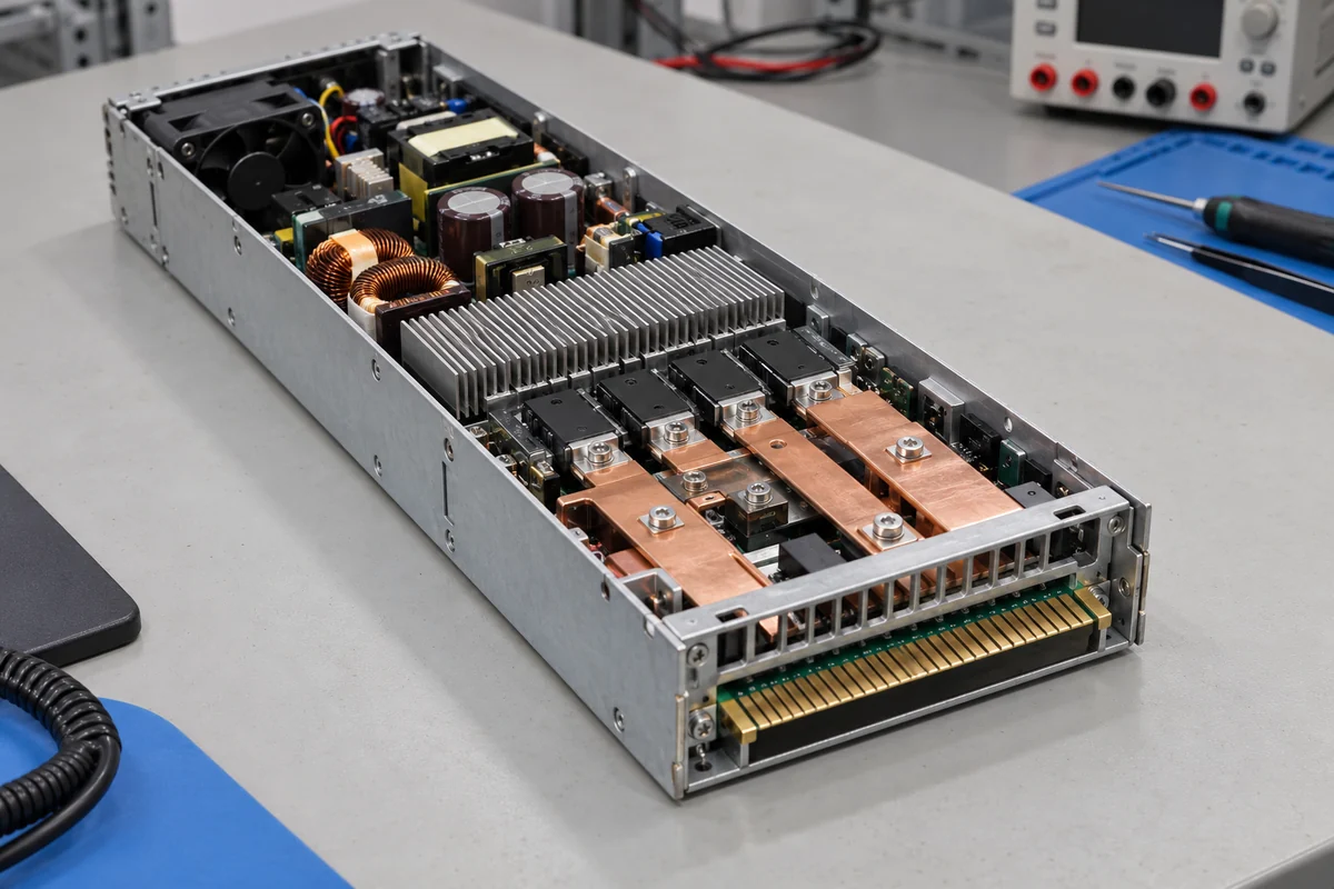
Synchronous rectification replaces some diode conduction with actively controlled switches, which can reduce loss in a suitable converter. It also makes control timing critical. Turning a switch on at the wrong point may drive reverse current or cause destructive overlap. Device on-resistance rises with temperature, and multiple devices may be needed to share high current. This is why “uses synchronous rectification” is informative but not a complete efficiency specification. The physical current path and control scheme determine how much of the theoretical conduction advantage survives in hardware.
The output does not become lossless after rectification. Copper planes, connectors, cable harnesses, sensing elements, and output filters all dissipate power. At high current, a few milliohms of additional resistance are meaningful. For 50 A, an extra 1 milliohm creates 2.5 W of resistive heating. That heat is concentrated in the specific contact or trace that carries the current, not spread harmlessly across the whole PSU. Mechanical design, contact force, plating system, and airflow therefore influence achieved electrical efficiency as well as reliability.
Some server architectures use a higher distribution voltage and convert it down nearer to processors or accelerators. A 600 W bus at 48 V carries 12.5 A rather than 50 A at 12 V, so a similar-resistance distribution path can dissipate less power. But the downstream conversion stage has its own loss, and the voltage choice imposes different protection, connector, and compatibility requirements. It is not honest to label the higher-voltage architecture universally more efficient without including the entire specified power path. The narrow lesson is that where conversion occurs changes which conductors carry high current.
Redundancy and auxiliaries still take a share
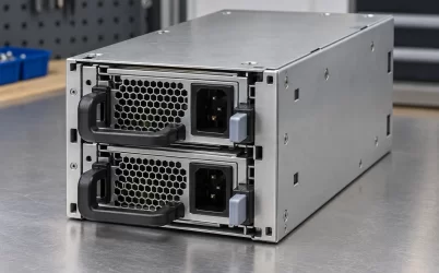
Hot-swappable server modules often need a method to prevent one failed or unpowered module from pulling down a shared output bus. An ORing diode can provide isolation but adds a forward-voltage loss. An actively controlled MOSFET arrangement may act as an “ideal diode” with lower conduction loss under appropriate conditions. It is not literally lossless: the MOSFET, controller, gate drive, board traces, and connector still consume or dissipate power. The isolation function is valuable even when it costs some efficiency, because its purpose is continuity during a fault or service event.
Current sharing is another system choice with an efficiency consequence. Two redundant modules sharing a load can each run at a different point from one module carrying most of it. Some systems have control strategies that reduce standby conversion loss by operating a spare differently at light load. Such strategies must preserve the required transition behavior when demand rises or a module fails. This is not an argument to run a generic redundant pair in an undocumented mode; it explains why module-level efficiency and the energy behavior of a complete redundant chassis need not be identical.
A PSU’s control electronics, standby output, telemetry, cooling fan, and housekeeping circuits can draw power even when the main load is small. At high output power, those watts are a small fraction of the total. At very light load, they can dominate the loss ratio. Modern control can reduce unneeded switching or fan operation where the design permits it, but a server PSU may need management communication and fault monitoring continuously. Cutting those functions simply to improve a no-load number would change the product’s role. The relevant engineering question is which losses can be reduced without sacrificing the host’s required behavior.
Fans illustrate why component and system efficiency must not be mixed. A fan can lower semiconductor temperatures and therefore some electrical losses, but the fan motor also uses power. More airflow may allow a denser converter or a higher temperature margin rather than maximizing a single efficiency reading. A result measured with one fan policy cannot necessarily be projected onto a different chassis airflow path. The power supply’s conversion efficiency, its own auxiliary consumption, and the server’s total cooling energy are related but distinct quantities.
Why the same circuit is not equally efficient everywhere
Even if a converter uses every technique above, its loss mechanisms do not scale identically with load. Fixed control and fan consumption remain when delivered power falls. Conduction loss grows strongly with current. Switching loss depends on frequency, voltage, transition timing, and control mode. Some stages may enter burst or discontinuous operation at light load; others do not. Consequently, a design optimized for high load can behave differently at a lightly loaded idle server. This explains the shape of an efficiency curve without repeating a tier-by-tier certification discussion.
Temperature changes the same devices. Copper resistance increases as it heats; MOSFET on-resistance and magnetic behavior are temperature dependent. A more efficient circuit can run cooler and thereby reduce some secondary losses, but the improvement is conditional on its actual cooling environment. Conversely, a circuit that wins at room temperature may lose part of its advantage in a hot chassis. Test data at specific input, load, and temperature conditions are needed to describe a specific PSU; this article explains mechanisms, not a rating for an unnamed unit.
Designers also have to allocate space and cost. A lower-resistance switch can be larger or more expensive. A larger inductor may cut loss but not fit the module envelope. An added parallel device can reduce conduction heat while increasing gate-drive complexity and board area. A different topology may improve full-load efficiency but demand more controls or change light-load operation. These trade-offs explain why efficient server PSUs are engineered as systems rather than assembled by selecting the lowest-loss part in each catalog column.
The useful answer is a loss path, not a badge
For a real unit, the meaningful evidence is its measured server PSU efficiency across operating loads, together with the actual output configuration and cooling method. Those measurements tell whether the combined circuit choices worked. The underlying reason modern server supplies can be efficient is not the server label itself: designers identify where watts are lost, then reduce the dominant losses without undermining isolation, control, protection, thermal limits, or redundancy.