Industrial power supply durability is not just a question of how long the converter’s components last. On a packaging machine, rail vehicle, compressor skid, or motor-driven cabinet, the installation can transmit vibration into an otherwise sound supply. A unit may have passed a published vibration test and still move differently when it is clipped to a flexible rail, mounted beside a drive, or restrained by heavy cables. This article examines that mechanical path: what a vibration claim actually covers, how the cabinet can change the motion reaching the PSU, and why a loose connection may look like a converter failure. General lifetime and MTBF questions belong elsewhere; here the concern is durability under an installed mechanical load.
The rating belongs to a mounted assembly, not a floating box
A vibration figure in a datasheet is meaningful only with its test conditions. The frequency range, acceleration or displacement, duration, direction, operating state, and mounting method all affect what has been demonstrated. A sinusoidal sweep and a random-vibration test do not impose the same history on a unit. A transport shock rating does not establish continuous operation beside a reciprocating machine. Even a number expressed in g cannot describe whether a DIN-rail clip stayed engaged, an output terminal remained stable, or the DC output held regulation while the unit moved.
Rockwell Automation’s 1606 power-supply vibration test procedure makes the mounting dependence unusually explicit. It describes both a DIN-rail snap method and a screw-secured method, specifies testing on perpendicular axes, and requires a stiff fixture so rail deformation does not amplify vibration at the supply. Its electrical setup observes the output during a powered vibration test. Those details apply to the specified 1606 testing program, not to every industrial PSU. They show why a bare claim such as “2 g vibration resistant” is insufficient without the accompanying fixture and operating conditions.
The product’s installation instructions can narrow the claim further. A vendor may qualify one orientation, one rail profile, or an additional retaining accessory for a heavier unit. Some shock tests are performed without power, while a separate operating vibration test monitors the DC output. Read the two claims separately. Surviving an unpowered shipping event is valuable, but it cannot by itself prove that a controller rail will remain uninterrupted during production.
The cabinet can amplify the motion at the supply
Imagine a motor bolted to a machine frame, a control cabinet fixed to that frame, a mounting plate inside the cabinet, and a long DIN rail fastened to the plate. The PSU sees the motion at its own mounting point, not merely the motion measured on the machine base. Each panel, bracket, fastener, and rail has stiffness and mass. At some frequencies, the assembly can move more at the supply than at the input point. At others, it can isolate the supply. Calling the whole cabinet “low vibration” from a single sensor location misses this transfer path.
A simple hypothetical example illustrates the problem without assigning a rating to a real product. Suppose the cabinet wall experiences an acceleration of 0.6 g at a particular operating speed, while a lightly supported rail section moves at twice that acceleration near the mounted PSU. The unit then experiences about 1.2 g at that point. This does not automatically mean failure: direction, frequency, duration, and the manufacturer’s documented limit still matter. It does mean that comparing 0.6 g at the wall with a PSU’s published test number would use the wrong location.
Rail length and support spacing matter because a long rail is not perfectly rigid. A supply mounted close to one end, a heavy neighboring device, or a cabinet plate with a local resonance can change its response. Cable bundles can also restrain one side of the housing and introduce another load path. A small change in motor speed may move the forcing frequency into or out of a structural resonance, explaining why an intermittent output appears only in a narrow speed band. None of this requires the converter’s electronics to be inherently defective.
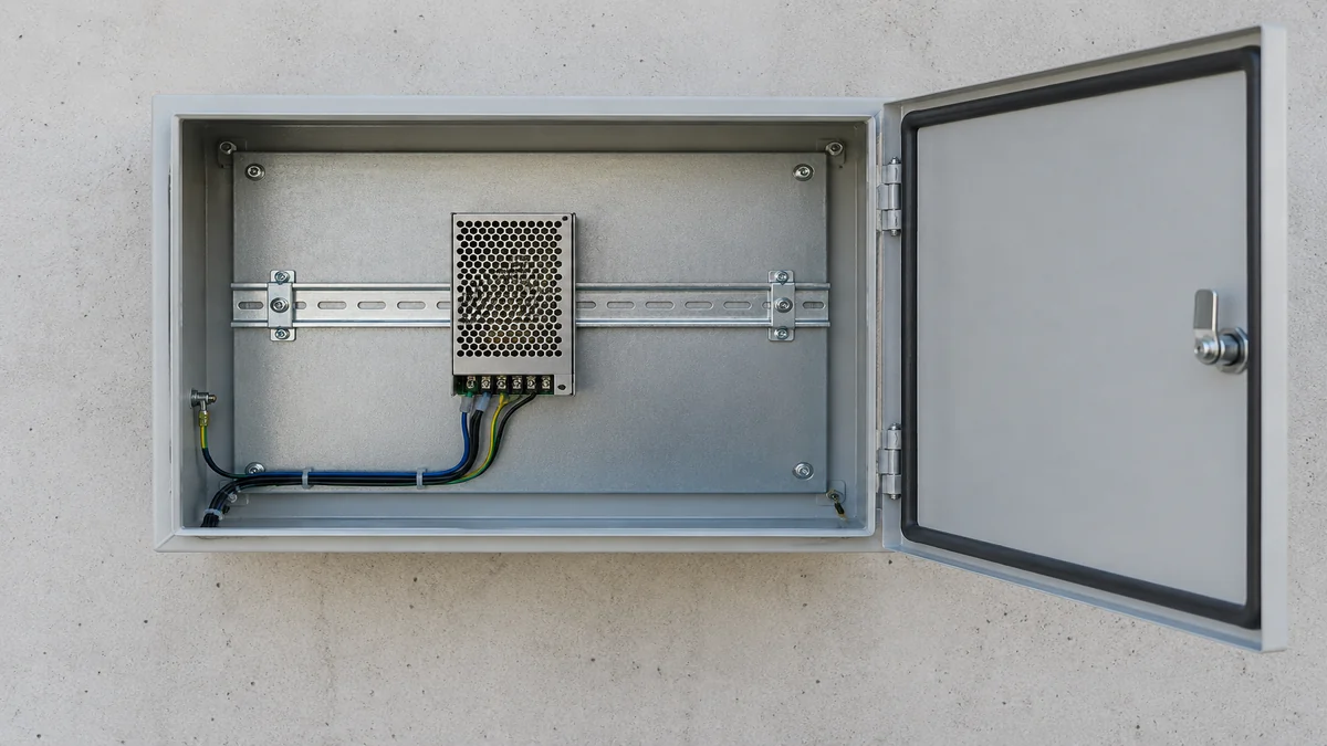
Clips, screws, and orientation change the load path
A DIN-rail clip is convenient, but its retention force and the rail’s profile are part of the installed assembly. A supply with a positive lock, a simple spring clip, or an approved screw-mounting kit can respond differently to repeated motion. That does not make one method universally superior. A secured mounting method helps only when the bracket, cabinet plate, fasteners, and approved clearances are appropriate for the exact model. Adding an improvised restraint can load the case unexpectedly or obstruct cooling.
Direction matters too. A vertical supply on a horizontal rail may be excited along the rail, perpendicular to it, or away from the mounting plate. The clip and rail do not resist these directions in identical ways. In a test report, separate axes reveal whether the unit was assessed in each direction; they do not prove that an installed bracket has the same stiffness as the laboratory fixture. Changing the mounting orientation may also alter convection and derating. A mechanical modification that improves retention but raises operating temperature is not an unqualified durability improvement.
Intermittent DC is not proof of an internal converter fault
Vibration can affect a connection before it damages the power-conversion circuit. A conductor termination that loses contact pressure may develop a changing resistance. A removable connector may move relative to its mating part. A cable tied rigidly to the cabinet can pull against a terminal while the PSU housing moves on its mount. The result may be a brief voltage drop at the controller even though the converter output at its own terminals remains within specification. Conversely, an internal crack or component failure is possible; the symptom alone cannot locate it.
The electrical consequence depends on load and timing. A marginal connection carrying a steady small current may show little obvious disturbance, yet a valve bank or actuator start can expose a larger voltage drop. A PLC reset can then be mistaken for an undersized PSU. If the supply’s own output indication remains stable while the load-side voltage falls, the distribution path deserves attention. If both collapse together, source protection, input quality, and the converter remain possible explanations. Indicator lights are clues, not universal diagnostic codes, and their meaning is model-specific.
Long-term mechanical stress can also present as heat rather than an immediate interruption. Increased contact resistance dissipates power at the interface; for illustration, 10 milliohms at 10 A dissipates 1 W. That calculation does not predict the temperature of an actual terminal, which depends on construction and heat transfer. It explains why a small electrical change at a concentrated contact can matter. An approved inspection may reveal discoloration or a damaged connector, but do not treat a visual check as proof that a live contact remains safe under vibration.
Cables and terminals need their own mechanical boundary
The cable between a fixed cabinet wall and a rail-mounted supply can become a spring. Too little slack transmits wall movement into the terminal; too much unsupported mass may oscillate and strain the entry point. Service loops, support points, bend radius, and allowable conductor size are installation details, not decorative cable management. Their correct form depends on the chosen PSU, terminal style, enclosure, and applicable electrical practice. Avoid inferring a universal tie-wrap spacing or torque value from a photograph.
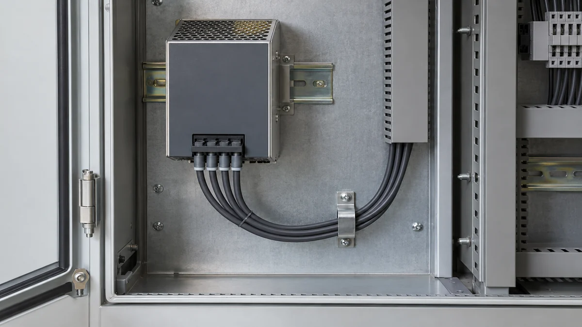
Power and signal wiring can fail differently. A high-current output termination may heat as resistance rises. A remote-sense or status connector, where present, may cause an apparent regulation or alarm issue after a brief interruption. Protective-earth continuity is a safety concern separate from DC continuity. Those paths should not be collapsed into one “connector problem.” Nor should the article be read as permission to handle a live terminal block: only authorized personnel following the equipment manufacturer’s isolation and verification procedure should inspect or correct wiring.
Operating vibration, shipping shock, and resonance answer different questions
Manufacturers may publish several mechanical claims because equipment sees different events. Operating vibration concerns repeated motion while the supply is energized and serving a load. Nonoperating vibration may describe transport or storage. Shock refers to relatively brief acceleration events; drop or bump tests add yet another handling profile. The relevant distinction is not which number is largest. It is whether the event resembles the cabinet’s real motion and whether uninterrupted output was part of the test acceptance criteria.
A test description should state what “passed” meant. Did the unit only remain mechanically intact afterward, or was output monitored throughout? Was it allowed to recover after a momentary interruption? Were the mounting clip and terminals inspected after the sweep? A machine control rail that cannot tolerate a short dropout needs more than a post-test visual pass. The test lab may report no damage under its fixture conditions while the integrator still has to address a cabinet resonance that the fixture intentionally avoided.
Resonance is easy to misunderstand. A power supply can have its own structural modes, but the rail-and-cabinet assembly can introduce additional modes. If the manufacturer’s test fixture was intentionally stiff, it provides controlled evidence about the unit; it does not certify every flexible field installation. Equally, an observed cabinet resonance does not prove the PSU is noncompliant with its datasheet. It may show that the installed boundary differs from the tested one. The practical answer is to identify and address the amplified mechanical path within the approved mounting design.
A cabinet example: the converter passes, the assembly does not
Consider a hypothetical bottling machine whose 24 V control rail resets briefly when a conveyor changes speed. The supply’s published operating vibration claim appears adequate when compared with a measurement on the cabinet door. Replacing the supply does not eliminate the reset. A later mechanical survey finds stronger motion near the middle of a long rail, where the supply and several heavy devices are mounted. The original datasheet has not been disproved: the door and rail were simply different measurement locations.
Suppose approved, nonintrusive electrical monitoring then shows that the PSU terminal voltage remains steady while the controller-side voltage dips during the same speed transition. The evidence points away from an internal converter interruption and toward the intervening connection or conductor path. A qualified technician, with the equipment isolated under the machine’s service procedure, finds a stressed output harness at the moving rail assembly. After the approved support and termination are corrected, the plant repeats the same operating transition and observes the result. This is an illustrative sequence, not a customer case or a universal diagnostic recipe.
Where the tested supply meets the moving cabinet
A durable industrial power installation aligns three boundaries: the manufacturer’s qualified PSU and mounting configuration, the cabinet’s motion at the actual PSU location, and the cable/terminal assembly that connects it to the machine. None can be substituted for another. A high-quality converter cannot stiffen a flexible rail, and a rigid bracket cannot repair a strained output contact. The finished assembly must also preserve electrical safety, cooling, and service access.
For a new machine, the useful mechanical evidence is concrete: an identified operating vibration profile at the intended mount, the exact supply and approved fixing method, its published test conditions, and a cable-support arrangement that does not load the terminals. For an existing fault, the most revealing observation may be the difference between motion or voltage at two locations during the event. Keep the conclusion proportional to those observations. A passed component test establishes what happened on that fixture; durability in the field depends on the machine that holds the component.