Moving 40 W of a server’s demand onto +12 V can change which 500W 2U server power supply remains a candidate, even when total DC demand stays at 450 W. The XEAL TC-2U50PD8 and IS-500S2UP specifications demonstrate that difference: the former limits its three +12 V outputs to 35 A combined, while the latter publishes a different main-output envelope. Two hypothetical load profiles below show exactly where their budget results diverge.
This comparison serves engineers examining multi-output power for a new or revised host. It compares complete products at their nominal static DC output boundary, without proposing interchangeable hardware. TC-2U50PD8 is a single supply; IS-500S2UP is a redundant assembly. Their matching 500 W ratings provide a useful arithmetic boundary, but their packaging and continuity functions remain different.
Two complete products share the comparison boundary
Both source specifications carry revision 1.0. The manufacturer product record identifies TC-2U50PD8 as end of life and IS-500S2UP as build to order. These are legacy documentation examples, not a survey of currently available products. Neither designation establishes inventory, delivery time, or the revision a seller would supply.
The IS-500S2UP document describes its redundancy as 500 W + 500 W = 500 W. Accordingly, this analysis applies the assembly’s published output limits once. It does not double them because two converters are present, and it does not compare a bare replacement cartridge with the complete TC supply.
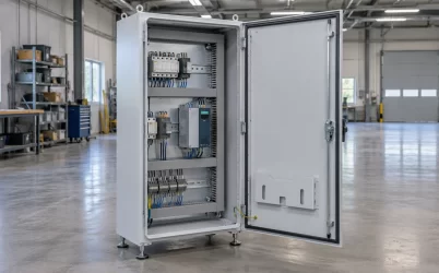
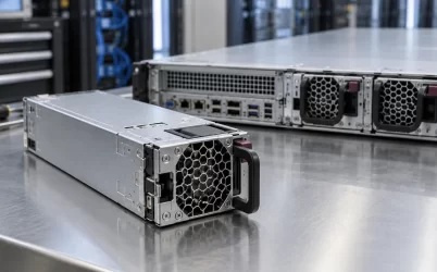
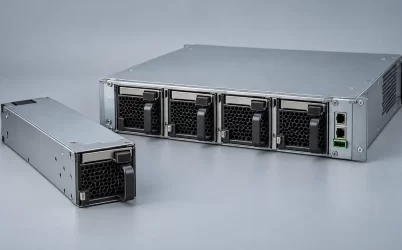
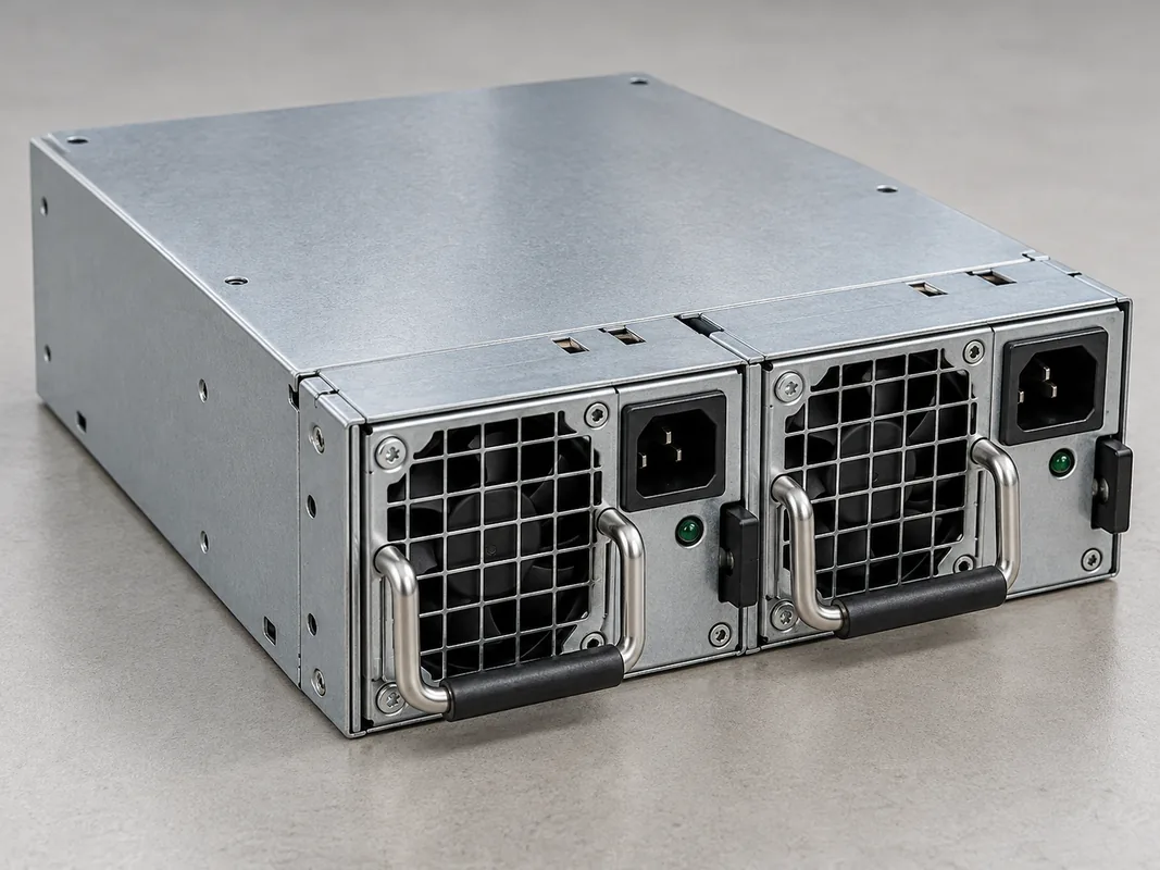
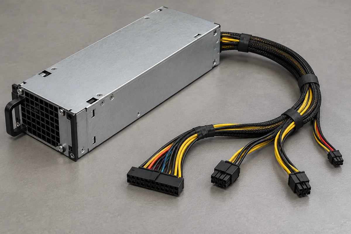
A redundant assembly includes the housing and module arrangement through which its converters serve the host. That physical boundary differs from a fixed single supply, even before output currents are considered. The illustrations accompanying this comparison are generic equipment illustrations; they do not identify either XEAL model or establish their dimensions, interfaces, or compatibility.
Readers replacing an installed unit have a different starting task. The existing 500W 2U PSU replacement article addresses preserving the host’s mounting, harness, and power architecture. Here, the narrower question is whether either documented output budget excludes a specified rail distribution before that integration work begins.
The TC supply imposes a separate three-branch ceiling
TC-2U50PD8 revision 1.0, sections 4.1.1 and 4.1.2, identifies three +12 V branches. Each has a 1 A minimum and 15 A maximum. A separate note limits their combined continuous current to 35 A. At nominal voltage, that combined restriction is 420 W. Three individually acceptable branch currents can therefore exceed the shared allowance.
The lower-voltage outputs introduce another shared restriction. The +3.3 V output spans 0.5–24 A, and +5 V spans 0.5–20 A, but their combined output must remain at or below 150 W. The document also lists −12 V at 0–0.5 A and +5 V standby at 0–2.5 A. All applicable outputs remain subject to the 500 W total ceiling. Its optional −5 V note supplies no basis for assigning an extra output budget here.
These restrictions can be written directly as simultaneous conditions: each +12 V branch stays between 1 A and 15 A; their sum stays at or below 35 A; +3.3 V and +5 V meet their individual ranges and 150 W group ceiling; and total DC output stays at or below 500 W. None is displaced by unused capacity under another condition.
The three branches also belong to a physical connector allocation. A calculated division of demand across +12V1, +12V2, and +12V3 is an assumption until the actual harness and receiving connections support it. Loads cannot be reassigned merely by changing spreadsheet columns. The examples stipulate branch demands to expose the shared restriction, rather than recommending rewiring.
That distinction matters even for the first profile, whose combined +12 V demand fits. Concentrating its 32.5 A on one documented 15 A branch would fail the individual limit. The equal split used below is a mathematical input, not evidence that an unidentified motherboard can distribute its demand that way.
The IS assembly nests 180 W inside a 480 W group
Table 2 of the IS-500S2UP revision 1.0 specification sets +12 V at 2–40 A, +5 V at 1–24 A, and +3.3 V at 1–24 A. Its grouped cells require careful reading: 180 W spans +5 V and +3.3 V, while 480 W spans those two outputs together with +12 V. The 180 W allowance sits inside the 480 W group.
Consequently, the 40 A +12 V entry is not permission to take 480 W there while independently drawing another 180 W from the smaller main rails. Their simultaneous power must fit the shared 480 W boundary. The complete assembly then remains subject to the separate 500 W maximum continuous total.
| Output restriction | TC-2U50PD8 revision 1.0 | IS-500S2UP revision 1.0 |
|---|---|---|
| +12 V current | Three branches, each 1–15 A; 35 A combined | 2–40 A |
| +3.3 V current | 0.5–24 A | 1–24 A |
| +5 V current | 0.5–20 A | 1–24 A |
| +3.3 V and +5 V combined | 150 W maximum | 180 W maximum |
| Positive main outputs combined | Apply the individual, grouped, and total restrictions together | 480 W maximum across +12 V, +5 V, and +3.3 V |
| Complete product total | 500 W maximum | 500 W maximum |
The IS table additionally lists −5 V at 0–0.5 A, −12 V at 0–0.8 A, and +5 V standby at 0.1–3 A. Their nominal maximum powers are 2.5 W, 9.6 W, and 15 W respectively. Those entries do not enlarge the 500 W total: drawing every listed auxiliary maximum alongside 480 W would exceed it.
Minimum currents matter to this comparison too. A load well below the total ceiling could still fall outside a documented minimum on a required output. The profiles deliberately retain positive-rail and standby currents within both products’ listed ranges; negative outputs carry zero demand. They therefore isolate the intended difference without hiding a minimum-load violation.
Keep 450 W constant and change where it is drawn
Profiles A and B are hypothetical continuous demands at nominal PSU output voltages. They are not measurements, approved server configurations, or proposed component lists. Every listed watt belongs to the same DC boundary, including standby consumption during the assumed operating state. Both negative rails are unloaded; no unspecified load is added afterward.
| Nominal DC demand | Profile A | Profile B |
|---|---|---|
| +12 V | 390 W; 32.5 A total | 430 W; approximately 35.83 A total |
| +3.3 V | 33 W; 10 A | 6.6 W; 2 A |
| +5 V | 20 W; 4 A | 5 W; 1 A |
| +5 V standby | 7 W; 1.4 A | 8.4 W; 1.68 A |
| Total | 450 W | 450 W |
For TC profile A, stipulate 130 W on each +12 V branch. Each branch then carries approximately 10.83 A, between 1 A and 15 A. Their combined 32.5 A is below 35 A. The +3.3 V and +5 V currents meet their individual ranges, and their combined 53 W is below 150 W. Standby demand is below 2.5 A, and 450 W is below 500 W. No listed static budget condition rejects A.
IS profile A also clears the listed arithmetic restrictions. Its 32.5 A at +12 V lies within 2–40 A; the smaller main outputs draw 10 A and 4 A. Their 53 W fits the 180 W group. Positive main-output demand is 390 + 33 + 20 = 443 W, below 480 W. Including 7 W standby gives 450 W, below the overall ceiling.
Profile B shifts 40 W onto +12 V while reducing the combined +3.3 V and +5 V demand by 41.4 W and increasing standby by 1.4 W. The net change is zero. This is a different stipulated host demand, not a claim that either supply can redirect output internally or that adding a converter would preserve power without conversion loss.
For TC profile B, stipulate +12 V branch powers of 144 W, 144 W, and 142 W. Their currents are 12 A, 12 A, and approximately 11.83 A. Each meets its individual range, yet their approximately 35.83 A sum exceeds 35 A. Equivalently, 430 W exceeds the nominal 420 W combined boundary by 10 W. The other outputs meet their stated ranges and grouped limit, and total demand remains 450 W. The combined +12 V restriction alone excludes B from this documented budget.
For IS profile B, approximately 35.83 A remains below the 40 A +12 V maximum. The 2 A and 1 A smaller-rail demands satisfy their minima and maxima. Their combined 11.6 W is below 180 W; positive main outputs total 441.6 W, below 480 W. Adding 8.4 W standby returns 450 W. Its listed static output budget does not reject B.
The remaining allowances explain why the two outcomes should not be reduced to a percentage load. In profile A, TC has 50 W below its total ceiling but only 30 W below its combined +12 V ceiling. Increasing only +12 V demand consumes the latter allowance first. For IS profile B, the positive main-output group has 38.4 W remaining, even though the individual +12 V entry appears to leave 50 W. Holding its other demands unchanged, the grouped restriction would be reached before the individual +12 V maximum.
The IS minimum currents also prevent interpreting its 40 A entry as an unconditional continuous 480 W allocation entirely to +12 V. Keeping +5 V at its 1 A minimum and +3.3 V at its 1 A minimum already consumes 8.3 W of the 480 W main-output group. The corresponding arithmetic ceiling for +12 V becomes 471.7 W before any additional main-rail demand. This derived boundary is useful for reading that table; it establishes neither a recommended operating point nor transient reserve.
The changed result is specific, but it is not host approval
The comparison produces an asymmetric finding: TC excludes profile B, whereas IS remains a candidate on the stated nominal DC arithmetic. Profile A is not rejected by either budget. That is more specific than observing that individual maxima cannot be added, because the same total demand produces a different candidate outcome using two exact manufacturer documents.
TC section 4.1.2 also supplies cross-regulation loading cases. These include individual outputs at maximum with others at minimum, plus named all-minimum and all-maximum cases. They describe prescribed combinations for regulation assessment. The all-maximum case is not permission to draw every output’s individual maximum simultaneously, and neither hypothetical profile becomes a manufacturer-tested case simply because its arithmetic fits.
Moving between A and B is not a transient-response test either. Their difference specifies two continuous allocations without defining transition time, slew rate, capacitance, or voltage excursions. TC’s separate transient requirements cannot be converted into a guarantee for that unspecified transition. Likewise, IS’s regulation statements do not establish measured behavior in an unidentified host.
Nor does IS’s budget result establish installed redundancy. The complete assembly’s documented architecture remains relevant, but host continuity involves its supported installation, module behavior, and required failure state. Mechanical fit, connector allocation, thermal conditions, and control timing remain outside these two static profiles. In particular, the manufacturer materials contain differing temperature statements for IS; this comparison assigns no installed thermal capability from them.
For the stipulated 450 W duty, the useful result is therefore precise: shifting demand to 430 W on +12 V crosses TC-2U50PD8’s documented combined boundary while remaining inside IS-500S2UP’s listed DC budget. A project retaining that distribution has a concrete reason to exclude TC under revision 1.0 and investigate IS further. It has no basis here to call the two products interchangeable, promise present availability, or authorize either for a particular server.