A nominal 52V open-frame power supply is not, by itself, evidence that a Power over Ethernet switch can deliver a compliant Type 4 port voltage. The board rating normally describes its DC output at specified terminals and conditions. Between those terminals and the power sourcing equipment (PSE) port sit conductors, connectors, control devices, and sometimes another regulator. The relevant question is whether the finished PSE maintains its required voltage at the port while the intended loads are operating. For IEEE 802.3bt Type 4, a published PSE voltage range begins at 52V. That makes a nominal 52V source a particularly tight starting point: ordinary downward variation or distribution loss can consume the entire apparent margin.
Find the point where 52V is specified
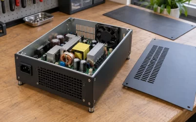
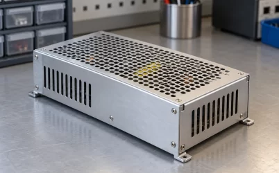
An open-frame AC-DC board is an exposed component intended for integration inside finished equipment. Its output specification may apply at a connector, screw terminal, or solder pad, with an input-voltage range, load range, ambient condition, and regulation tolerance in the manufacturer’s documentation. The measured output at no load may not equal its voltage near full load. A remote-sense feature, if offered and correctly connected, can compensate for part of a distribution drop, but it cannot be assumed from the nominal voltage printed in a product listing.
The Ethernet port is downstream. A switch may take the board rail through an input fuse, PCB copper, a distribution connector, PSE controller, and a controlled output device before applying power to a cable. Some designs include a DC-DC stage that creates a separate PSE rail. Others feed the PSE more directly. The source voltage therefore cannot be translated into port voltage without the particular circuit. The phrase “52V open-frame power supply” identifies a possible upstream component, not the location at which an IEEE voltage limit is automatically met.
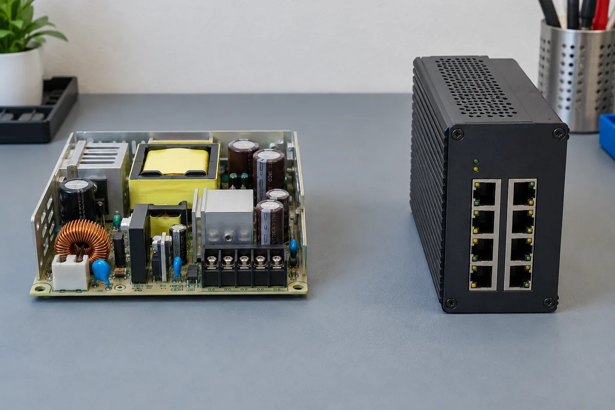
Location matters even when a bench measurement looks reassuring. Probing the board output while the PSE is idle can miss a sag that appears when multiple ports energize. Measuring at a connector just ahead of the controller still omits losses across the controller’s switching path. The equipment designer needs the permitted voltage at the PSE power interface under the operating conditions covered by the product’s claims. A purchaser replacing a board inside an existing switch should use the switch maker’s approved electrical and mechanical replacement specification, not a matching nominal-voltage sticker.
Why Type 4 exposes the missing margin
The Microchip PoE standards overview lists PSE voltage ranges of 44–57V for Type 1, 50–57V for Types 2 and 3, and 52–57V for Type 4. These are ranges at the PSE boundary, not universal output settings for an AC-DC board. Type 4 is associated with the higher-power IEEE 802.3bt classes. Its 52V lower limit is the decisive detail for this question: a source nominally set to 52V offers no numerical allowance for a downward source tolerance or any positive drop between source and port, unless the design restores the voltage by a supported means.
Type 2 or Type 3 has a lower published PSE minimum of 50V, so the same nominal source may appear to leave 2V of theoretical headroom. Even that is not a guaranteed 2V budget. The board may be below nominal within its specified regulation band; the path drop grows with current; the PSE may need additional internal voltage to operate correctly. It is also possible for a particular design to regulate the port rail independently. The useful comparison is not “52 exceeds 50,” but “the minimum port voltage in the finished equipment exceeds the applicable minimum under its specified operating envelope.”
Do not substitute the powered device’s voltage for this port-side requirement. The PSE launches power into Ethernet cabling; copper resistance and connections create further loss before the powered device (PD) receives it. Standards account for different PSE and PD power boundaries. A voltage measured at a distant camera answers a different question from the PSE-port voltage, while a board-terminal measurement answers an earlier one. The three locations should be named explicitly in a design discussion so a passing number at one point is not mistaken for proof at another.
Trace a hypothetical half-volt before changing the set point
Consider a simplified internal DC path, not a specification for a Powernexu product or a real switch. Suppose a 52.0V board feeds the PSE through wiring, a connector, copper, and switching elements whose combined effective resistance is 0.12 ohm at a chosen operating point. If 4A flows through that shared path, Ohm’s law gives a 0.48V drop. The PSE would see approximately 51.52V if the board actually held 52.0V at its terminals. The same resistance would dissipate 1.92W in that path. This arithmetic illustrates why even a small-looking impedance matters near a 52V Type 4 floor; it does not assert that 0.12 ohm or 4A describes any particular product.
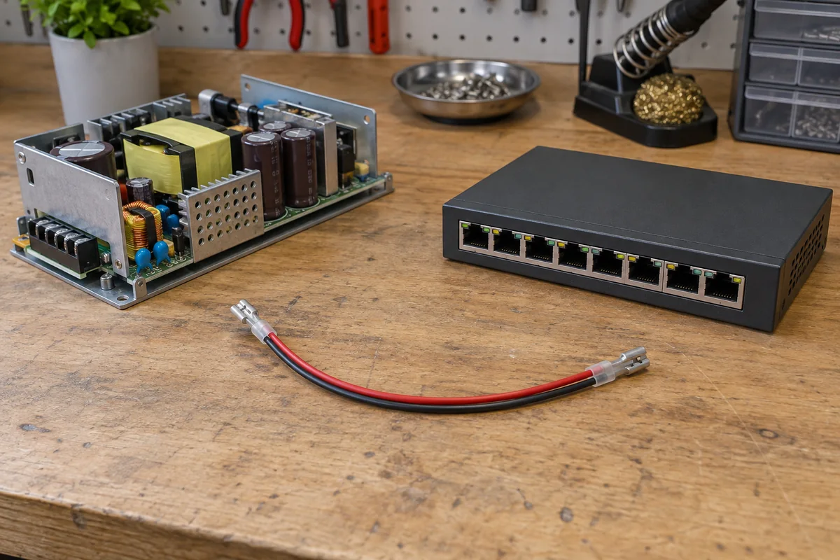
The real path need not behave as a single fixed resistor. MOSFET on-resistance changes with temperature. Connector resistance may rise with aging or poor contact. Copper heating changes its resistance. A current surge can briefly increase drop while the board’s control loop is still responding. A controller may also impose a deliberate voltage or current behavior that is not captured by the simple calculation. These effects are reasons to examine the actual rail at the relevant load and temperature, not reasons to multiply an arbitrary safety factor until the result looks conservative.
The board’s own voltage tolerance belongs in the same envelope. If a hypothetical nominal 52V source could deliver 51.5V at its low allowed limit, the example path would leave about 51.02V before other losses. Conversely, setting the source higher to cover the low-load case may bring the port close to its upper limit when the load and path drop are small. Those example values are illustrative, not standard tolerances. Only the selected board’s documentation and the finished PSE’s measured or specified behavior establish the actual endpoints.
This is why the first response to a low port voltage should not automatically be “turn the adjustment screw.” A trim control, when present, has a documented range and may alter protection thresholds, standby behavior, or other rails supplied from the same board. The PSE controller and capacitors also have voltage ratings. If the board is a replacement part, changing its setting can move the equipment outside the host manufacturer’s supported configuration. A shorter, lower-resistance distribution path or an appropriate regulated PSE stage may be the real design solution, but neither can be prescribed without the circuit.
A board may be 52V while the port is deliberately higher
There are legitimate architectures in which a 52V nominal board participates in a Type 4 system. A properly specified downstream converter may raise and regulate a PSE rail within its permitted range. A supported board may have a controlled output setting above nominal, with the minimum still high enough after path loss and the maximum remaining acceptable at light load. A PSE assembly could also be designed around a source whose published range, rather than its marketing name, covers the needed conditions. None of these arrangements follows merely from the fact that a board is sold as “52V.”
In such a design, the regulated PSE rail is the component that closes the voltage gap. It must carry the intended current with its own conversion loss and thermal burden, and it must behave through startup and load changes. Calling it a “boost” stage does not prove that the finished port meets Type 4 limits; the stage has to be present, rated, and integrated into the actual PSE. A diagram or datasheet that shows a 52V AC-DC board upstream of a second power stage is therefore not contradictory. It describes two voltage domains that should not be collapsed into one nominal number.
The high end matters as much as the low end
A source chosen solely to rescue the heavy-load minimum can create trouble at light load. The Microchip overview gives 57V as the upper PSE voltage boundary for all four listed types. When fewer ports draw power, resistive drop in the shared path falls. If the upstream setting was raised to compensate for full-load loss, more of that setting can reach the port. The board’s positive tolerance, line regulation, overshoot, and the PSE rail’s control behavior become relevant at the high end. The finished equipment needs both endpoints inside its supported range.
This two-sided constraint also changes how a voltage reading should be interpreted. A steady 53V observed at one port with one device attached is useful evidence for that particular state, not proof that the voltage remains acceptable through every permitted input and port combination. Measuring only the full-load case could miss a high-voltage condition at minimal load; measuring only idle could miss the low-voltage condition that motivated the question. The intent is to understand the rail’s actual operating envelope, not to collect a single reassuring number.
Port voltage is not the entire PoE function, either. Detection, classification, current limiting, fault response, and pairset behavior are performed by the PSE circuitry. A compatible DC source cannot supply these features on its own. The narrower issue here is whether the rail presented to that circuitry has sufficient voltage margin.
Heat inside the enclosure changes the board-side answer
An open-frame board’s data may include derating with ambient temperature, input voltage, mounting orientation, or airflow. Those conditions belong to the board output claim. A tightly packed PoE switch enclosure can expose the board to air already warmed by Ethernet electronics and PSE switches. A 52V reading on an open bench does not establish the same output behavior behind a port panel under sustained high demand. If the supply enters current limit or thermal protection, its output may droop or cycle rather than merely shift by a tidy regulation percentage.
Physical installation affects both heat and electrical drop. Longer harnesses routed around a fan duct add conductor resistance. A compact connector may be electrically adequate at room temperature but run hotter at the intended continuous current. Shortening the route can help voltage margin, yet moving the board into a stagnant pocket may reduce its thermal margin. The mechanical layout must respect the board’s documented mounting, isolation, clearance, grounding, and airflow requirements; open-frame does not mean safe to leave accessible or unsupported inside the host.
What a 52V part number can honestly establish
A 52V open-frame listing can establish that a manufacturer offers an AC-DC output around that nominal value, along with whatever input, current, tolerance, adjustment, cooling, and safety information its datasheet actually publishes. It cannot establish that the part is interchangeable with a switch’s approved supply, that a particular PSE operates at Type 4, or that the Ethernet port stays inside 52–57V under load. Powernexu does not need an invented 52V model to explain the engineering boundary; a real product comparison would require a verified candidate datasheet and the host equipment’s electrical requirements.
If the finished product promises Type 4 and its port rail is fed directly from a nominal 52V board with unavoidable positive drop, the label alone cannot support that promise. An independently regulated rail, a documented higher source setting, or a different source may close the gap within the permitted upper limit. Until one of those mechanisms is shown in the actual design, “52V” remains a board-terminal description, not a Type 4 compatibility claim.