CRPS2200CLM is Great Wall Power’s 2200 W, 12 V CRPS module in a 265 × 73.5 × 40 mm housing. Its public record lists two main-output currents, 90.2 A and 180.4 A, but leaves the input-voltage field blank and does not explain which operating condition applies to either current. A buyer can identify the module and screen a long PSU bay from that record; the buyer cannot infer full output on a particular facility feed or interchangeability with another 2200 W CRPS module. The key planning question is whether the host has the physical length, electrical interface, and documented operating condition for this exact CLM part.
The combination of a long enclosure and a 12 V output gives this model a narrower use than a generic “2200 W server PSU” search suggests. This article reads the published data as a bounded product specification, then follows the consequences through the rear power bay and 12 V distribution path. It also separates CRPS2200CLM from the shorter CRPS2200D2 and the long-body, 54 V CRPS3500CL5M; similar names and outer dimensions do not establish a shared connector or an approved substitution.
Read the two published 12 V current entries separately
Great Wall’s CRPS2200CLM product record identifies 2200 W output, +12 V at 90.2 A and 180.4 A, and +12VSB at 3 A. The main entries are best treated as two published current values for the same nominal 12 V output. They must not be added to claim 270.6 A of capacity. The record does not say whether the entries correspond to different AC input ranges, DC input, temperature conditions, or another rating distinction. A table that silently assigns them to low line and high line would manufacture a specification that the page does not provide.
The arithmetic helps interpret their scale while preserving that missing context. At a nominal 12 V, 90.2 A represents about 1,082 W on the main rail, while 180.4 A represents about 2,165 W. These are calculations from the listed voltage and currents, not fresh manufacturer output guarantees. The small difference between 2,165 W and the 2200 W product label should not be “corrected” by assuming a precise rail voltage, a combined standby allowance, or a rounding convention. Those details require the exact technical sheet. What matters immediately is that the two numbers imply substantially different usable load bands if they indeed describe alternate conditions.
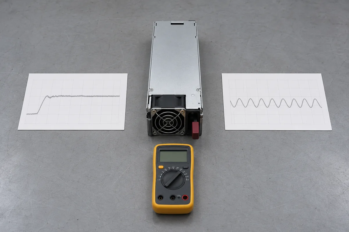
Imagine a proposed server whose documented worst-case 12 V demand is 130 A. That value sits above 90.2 A and below 180.4 A. The public listing alone therefore cannot approve the module for the proposed inlet conditions. It tells the integrator exactly which missing information to request: the condition attached to each current entry, the allowed continuous load, any temperature or altitude derating, and the revision of the module to which the data applies. The example is a comparison method, not a claim that a particular server has a 130 A load.
The +12VSB / 3 A entry is a separate standby output. It may be relevant to a host controller before the main 12 V path is enabled, but a standby rating says nothing about the position of that contact on the mating connector or its sequencing in a specific chassis. Treat the public numbers as a shortlist for electrical design review. They do not replace a pin map, power-good behavior, control timing, or a host qualification statement.
A 265 mm body changes the receiving bay
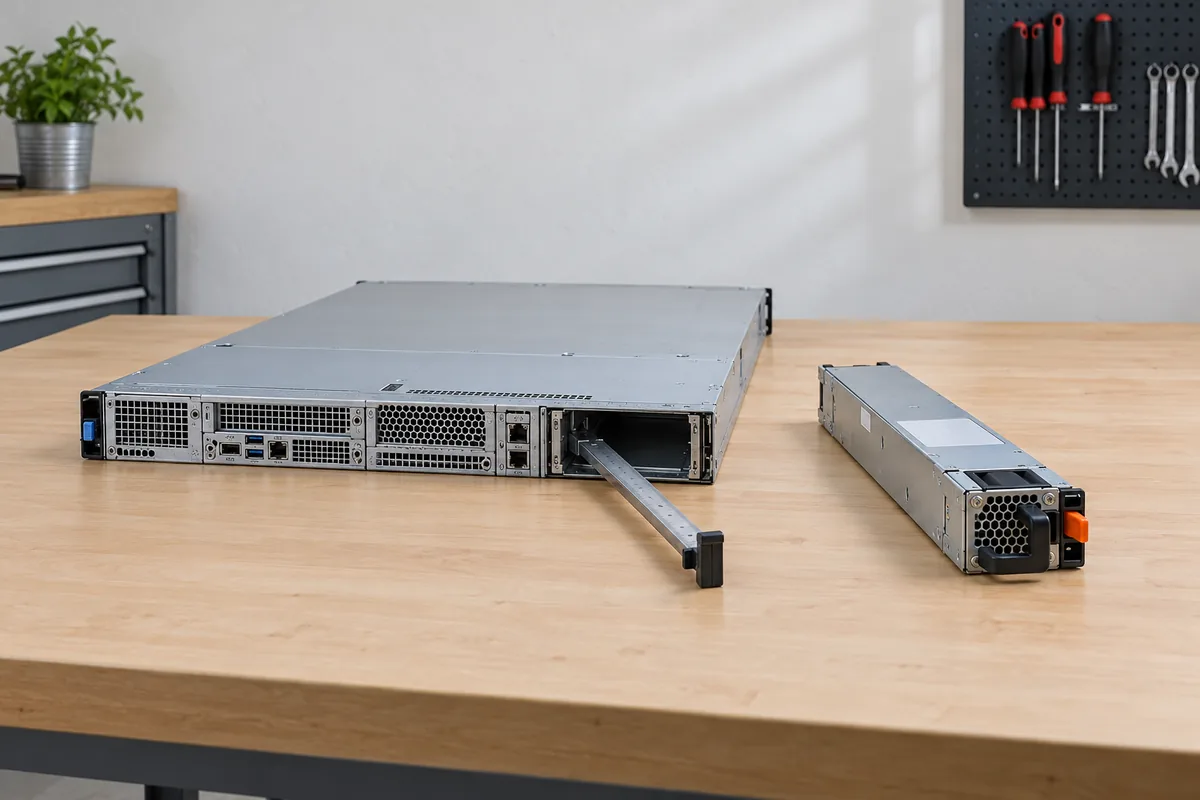
At 265 mm long, CRPS2200CLM occupies 80 mm more depth than Great Wall’s published 185 mm CRPS2200D2 envelope. Their listed width and height are both 73.5 × 40 mm. That shared cross-section can make the two units look related in a catalog thumbnail, yet the added depth changes where the module reaches inside the server. It can meet a fan wall, a power distribution board, a cable bundle, or a structural member that was clear with the shorter part. It also changes the path available for insertion and extraction at the rear of the chassis.
A useful fit study starts with the host’s complete bay drawing, not the bare outside dimension. The 265 mm value describes the product envelope; the manufacturer page does not publish a complete installation drawing showing connector engagement depth, guide rails, latch geometry, handle projection, or tolerances. The metal body may appear to fit an open bay while its contacts cannot reach the mating plane, or it may bottom against the backplane before its retention mechanism locks. A panel-mounted connector in a nearby location can also interfere with the handle or the extraction path. These are distinct failures, and measuring free volume alone catches only some of them.
Measure the internal run from the rear opening to the mechanical stop and locate the backplane connector relative to the latch datum. Then consider the space needed to remove a module without bending nearby power cables or hitting a rack door. For a dense server, the rear face may contain network ports, power cords, and service labels around the PSU. If the CLM housing reaches farther toward the center, its interior clearance must be checked under a closed cover with fans and distribution hardware installed. A top-open photograph may hide an obstruction that appears only in the assembled configuration.
The manufacturer marks airflow direction as FR and lists operation from 0 °C to 55 °C. Neither item identifies the host’s airflow direction by itself. Ask for the exact meaning of FR for this revision and compare the installed module’s intake and exhaust with the server’s pressure zones. A long module can pass through more of the chassis air path than a short one; recirculation or a blocked inlet may matter even when the external form is mechanically accepted. The 55 °C endpoint is an operating-temperature listing, not proof of 2200 W output at that endpoint. Full-load thermal claims need the manufacturer’s temperature-dependent rating and the host airflow data.
The 12 V destination matters more than the wattage label
CRPS2200CLM delivers a nominal 12 V main output. In a server, that current generally reaches a power distribution board or bus structure before local converters produce the rails needed by processors, memory, storage, and other loads. At the higher listed current, contact resistance and copper distribution become material engineering questions. For illustration, a 1 milliohm resistive element at 180.4 A would dissipate roughly 32.5 W by I²R. This is a hypothetical calculation, not a measured loss in the CLM product. It shows why a high-current path cannot be approved from a PSU rating alone: the actual contact resistance, number of parallel contacts, bus geometry, and cooling determine whether the host path is suitable.
The current path has several boundaries. The PSU’s mating power contacts must align with the receiving connector. The backplane must carry the applicable current continuously and through relevant transients. The distribution board must route it without exceeding its own temperature rise or voltage-drop limits. Local converters and any accelerator branches need their documented input range during fast load changes. A module may be capable of delivering a published current in its specified test fixture while an unrelated server backplane is rated for less. No public CRPS2200CLM product record establishes a universal PDB match.
Where two modules operate as a 1+1 redundant pair, the load after one unit is lost belongs to the surviving unit’s applicable operating band. Two installed 2200 W labels do not automatically provide 4400 W of fault-tolerant capacity. If the 90.2 A entry applies to the site’s input condition, a host drawing 130 A could run while both units share and then exceed the survivor’s permitted current after a failure. Without the rating-condition table, that remains a scenario to resolve rather than a claim about this model. Also verify whether the host supports the exact module revision and whether the pair is required to use matching assemblies.
Similar Great Wall names lead to different design questions
The closest misleading neighbor is CRPS2200D2. Great Wall lists it at the same nominal 2200 W and 73.5 × 40 mm cross-section, but its body is 185 mm long. It also publishes three main 12 V current entries, 91 A, 164 A, and 181 A, and gives a stated input range in the catalog. None of those facts makes it a shorter version of CRPS2200CLM that can be swapped at will. The longer CLM housing, its two-current listing, and the blank input field create a different information set. Its suffix must remain in every purchase order, drawing, and service label.
The long-body neighbor CRPS3500CL5M raises a different trap. It shares Great Wall’s 265 × 73.5 × 40 mm published envelope and FR notation, yet the manufacturer lists a 54 V main output and 3500 W rating for that model. A 54 V source cannot be substituted into a 12 V distribution path because the outer metal dimensions match. A connector that appears similar in a photo is not a safe compatibility test. The CL5M article naturally centers on a 54 V downstream architecture and its 3500 W mechanical requirements; the CLM decision here centers on a specific 12 V current path within a long bay.
Read the blank input field as an unresolved engineering variable
The Great Wall CRPS2200CLM listing leaves “Input Voltage” empty. Powernexu’s CRPS2200CLM product page likewise does not supply an input range in its available model data. The omission is consequential because the inlet voltage can affect which published current entry is available. It would be tempting to copy the AC and DC range from CRPS2200D2 or another family member, but that would confuse a neighboring product’s data with a specification for this exact part.
For a facility design, write the actual source first: voltage at the module inlet, AC frequency or DC polarity as applicable, allowable deviations, plug and cord configuration, and the condition after transfer to the alternate feed. Ask Great Wall or the qualified supplier for the CLM input and output rating table tied to the offered revision. The answer should identify which 12 V current entry applies at each intended input and whether full output is maintained across the expected ambient range. The public Platinum designation is also insufficient for a numerical energy model. A measured efficiency curve at the expected load and input is needed to calculate input power and heat with useful precision.
When the CLM specification is enough to move forward
The published CLM facts are enough to start a targeted mechanical and electrical discussion. A 265 mm receiving bay, nominal 12 V distribution, and load below a verified applicable current band are plausible screening conditions. They are not a release for a particular host. The useful next artifact is a model-specific technical sheet or written cross-reference that joins the CLM revision to its input conditions, mating interface, thermal rating, and server platform. If the part is intended for 1+1 service, the document must also establish the single-module load that remains after a failure or removal.
That is the practical meaning of the two numbers in the public record. Their relationship remains unexplained, and the blank input field prevents assigning either published value to a real feed without further documentation. Preserve the 265 mm bay requirement and the 12 V architecture in the system record, then obtain the missing rating map before sizing or substituting the module. A catalog can identify CRPS2200CLM accurately; only the complete manufacturer and host records can make it an approved part of a running server.