Industrial AC–DC power conversion and selection should establish the required direction of energy flow before comparing converter levels. A machine that only takes power from its AC source presents a different requirement from one expected to return energy across that same interface. “Three-level” describes a conversion arrangement; it does not, by itself, establish bidirectional operation. A design can have an attractive forward-power operating point and still offer no supported route for energy arriving from its DC side.
Start with the complete path from the AC input to the machine’s DC loads. This article then narrows the question to the three-phase AC–DC front end: must that boundary transfer energy only toward the DC bus, or in both directions under defined conditions? The answer is a design requirement, not a feature inferred from the number of voltage levels or a generic industrial label.
Draw the second arrow before choosing the front end
During ordinary powered operation, a converter delivers energy from the AC interface to a DC link and the equipment downstream. A second arrow appears only if the application requires energy to travel back across that interface. It is useful to draw it separately because many other events can return energy to a local bus without establishing a return path to AC.
Consider a hypothetical machine with a drive and a DC link. In one operating interval the drive consumes energy to move a mechanism. During a documented deceleration condition, it returns some energy toward its DC input. That identifies the drive as a source during that interval. It says nothing yet about whether the AC–DC stage can accept that energy or whether other hardware separates the drive from the front-end link.
The electrical boundary must therefore be named. Returned energy at a drive connector, accepted energy at a DC-link port, and exported energy at an AC interface are three different claims. A system can satisfy the first while lacking the other two. A description such as regenerative operation is incomplete unless it identifies the origin, destination, and supported path between them.
This also prevents a specification error in the opposite direction. Not every machine needs a reversible AC–DC front end. A design may handle the relevant energy through a documented dissipative or storage arrangement, or its permitted operating pattern may not return energy to the common link. The requirement should follow the actual process and its allowed states, rather than adding bidirectionality because it sounds more capable.
Keep the energy balance conditional. Another branch may consume some returned power while the machine operates, but its presence does not establish an assured destination. That branch can change state, disconnect, or reduce consumption. If the design depends on it, its availability belongs in the requirement. Incidental simultaneous consumption should not silently become the mechanism that prevents excessive bus voltage.
Three levels do not settle the direction question
Texas Instruments’ July 2024 Conversion Topologies for Three-Phase Industrial Systems provides a useful contrast. It describes a T-type three-level arrangement capable of bidirectional operation and a Vienna three-level rectifier with unidirectional power flow. Those examples demonstrate why the three-level description cannot establish reversal capability. They are topology examples from the report, not a claim that every implementation bearing either name has a complete, approved regenerative function.
The distinction is more useful than a ranking of the two names. If the machine requires reverse transfer across the AC–DC boundary, a candidate whose documented function is unidirectional does not meet that requirement merely because it offers three levels. If only forward transfer is required, the absence of reverse operation may be entirely consistent with the job. Other characteristics then become the relevant comparison.
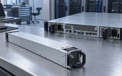
A complete enclosure can contain several conversion and control regions; the housing does not identify which stage a returned-energy path must cross. Separate the concept of a circuit’s available switching states from the behavior supported by a finished converter. Semiconductor arrangement, drivers, sensing, control, protection, and the rest of the implementation have to support the proposed operating mode. A topology diagram can explain why a direction is possible in that arrangement. It cannot independently establish the operating envelope or fault response of an unidentified product.
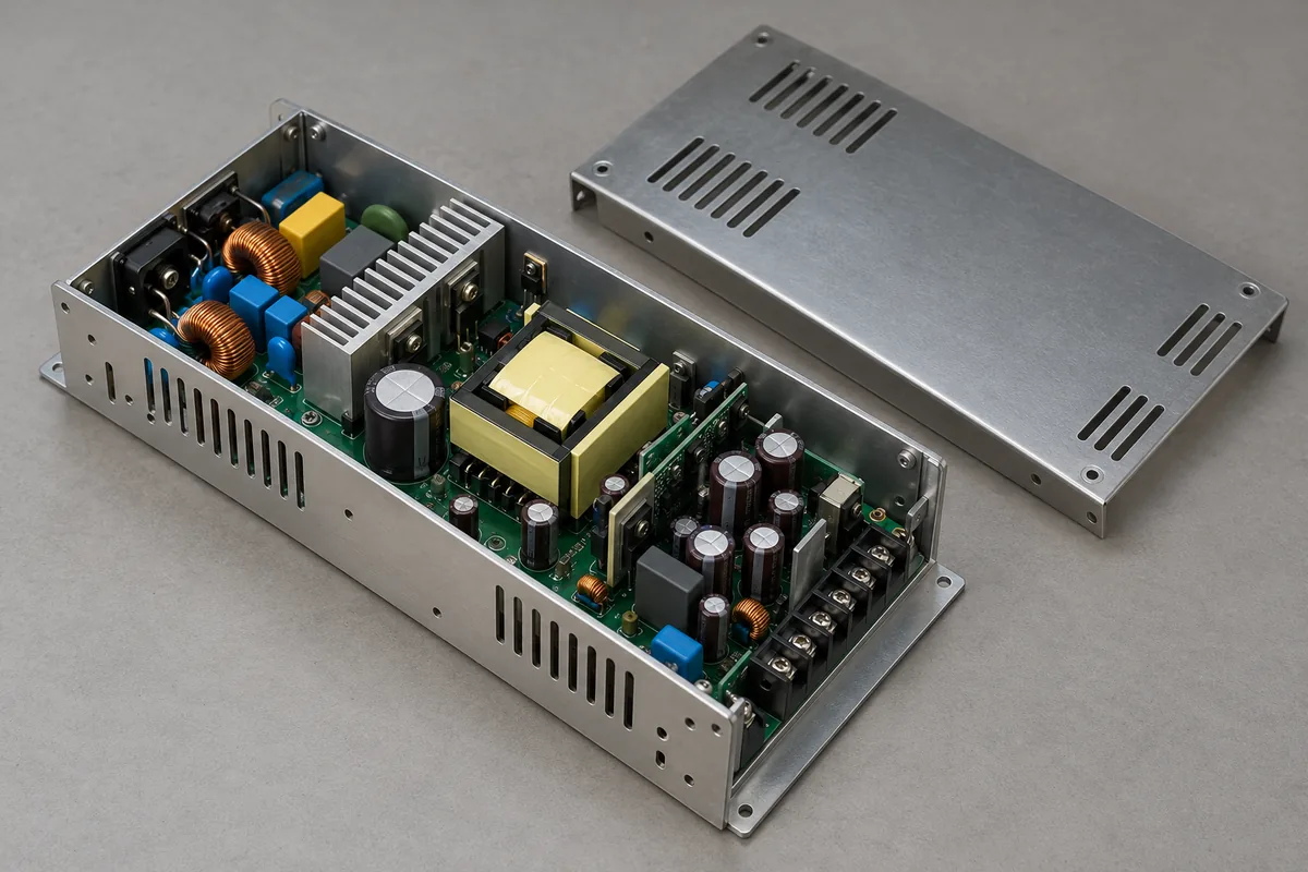
Likewise, a bidirectional topology should not be turned into a promise of equal capability in both directions. Forward and reverse limits, permissible DC and AC conditions, transition behavior, thermal duty, and control restrictions need their own documentation. A large forward-power rating is not evidence of an equally large reverse rating. The same principle applies when the proposed converter is only one stage inside a larger assembly.
At this point the selection has a useful first gate: does the documented energy direction match the application? Passing it does not choose the final topology, but it removes a category error before semiconductor comparisons, modulation choices, or detailed loss calculations absorb engineering time. Failing it means the architecture or the energy requirement needs to change.
A reversible stage still needs a reachable destination
Suppose the hypothetical machine uses a front end whose documentation supports reverse transfer. Trace the proposed returned-energy route again. A downstream converter may permit energy toward the load but not toward its input. A blocking device or an opened contact may separate two sections of the DC system. The front end cannot remove energy from a node it cannot reach through a supported path.
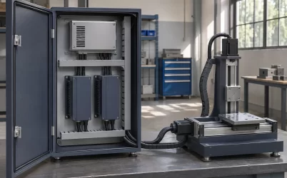
Physical proximity does not close that gap. A drive beside a power-conversion enclosure can share a cabinet while belonging to a separate electrical domain. The assembly drawing should identify the actual connection boundary, any intervening conversion or isolation stage, and the conditions in which the path exists. An illustration of adjacent equipment is useful for locating these responsibilities, not for proving reverse-current permission.
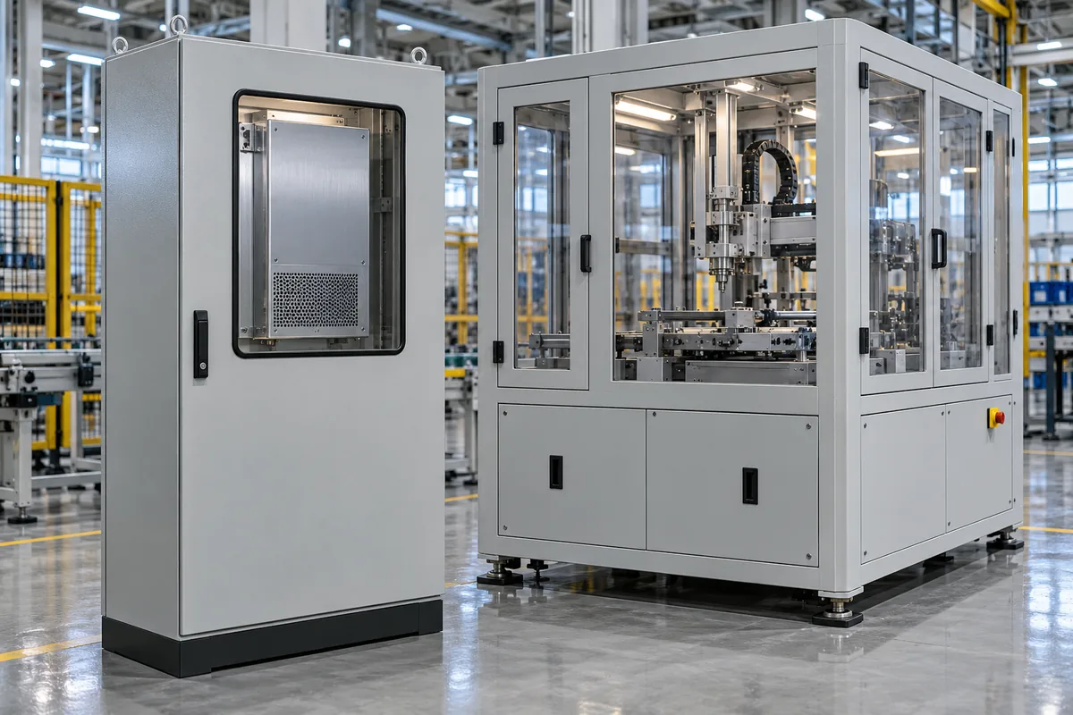
The intended destination must also remain available. An AC interface that normally receives power is not an unconditional sink under every supply state. If reverse operation depends on the connected AC system meeting particular conditions, loss of those conditions changes the machine’s energy-management problem. The equipment needs a documented response rather than an assumption that the front end can always export whatever arrives.
This does not prescribe a grid connection, an islanded operating mode, or a protective setting. Those belong to the equipment and installation requirements. The narrower engineering point is that reverse-capable conversion and an available destination are separate permissions. Both must hold for the claimed path to work in a particular operating state.
A local energy destination has different limits. Storage can accept energy only within its supported state and charging envelope. A dissipative arrangement has power, energy, repetition, and thermal conditions. These mechanisms should not be described as equivalent to returning energy through AC, even when each can help manage a DC link. They answer the same energy-balance problem through different physical paths.
Nor does an output overvoltage response necessarily solve that balance. A converter can stop adding forward power without removing incoming energy from another source. A protection threshold or shutdown action is therefore not a substitute for a documented absorption or transfer capability. Identify what the responding device actually does with the energy, rather than only where its alarm occurs.
Describe the operating cases that keep the arrow valid
Write a small set of machine states before calculating a preferred front end. Normal forward operation is one case. A repeated interval of returned energy is another. Startup, a commanded stop, a disconnected downstream section, and loss of the normal destination can introduce different constraints. Use only the cases relevant to the actual process, while preserving those that change where the energy can go.
For each case, state which devices are connected and which controls are active. A route that works after the DC link has been established does not automatically describe startup. A controlled operating stop need not have the same connections as an interruption initiated by protection. The desired final voltage alone does not specify the path through those intermediate states.
The timing relationships matter without requiring a universal sequence. If a contact opens before returned energy has ceased, the energy can remain on the side no longer connected to the selected destination. If another load is deliberately retained to consume energy, the design needs to establish when it is available and when it is allowed to disconnect. These are connectivity and control questions, not reasons to override a machine’s established safety behavior.
Repeated operation needs another qualification. A destination that accepts one event from a favorable initial state may have less room or thermal margin for the next. The system description should include the permitted repetition and recovery conditions. An average over a long production interval can conceal a demanding short event, while a peak value without duration cannot establish the required energy handling.
A useful hypothetical acceptance statement is consequently conditional: during the specified machine transition, returned energy reaches the designated link through the supported downstream path, and the chosen destination remains available within its documented limits. If one condition is absent, the equipment takes its defined alternate response. This is more meaningful than asking whether a converter is generally regenerative.
A changed machine option can expose the same distinction after the initial design. Adding a second drive may introduce another energy-producing state even when the normal forward demand remains within the original rating. Conversely, replacing a drive with one that keeps braking energy local can change what reaches the common link. Preserve the operating-case description when equipment options change. The front-end selection remains justified by the path and states it actually supports, rather than by a permanent label attached to the cabinet.
Observations should follow those boundaries. Current direction and voltage at a local drive port answer different questions from power at the front-end AC interface. A rise in DC-link voltage shows an energy imbalance at that node, but does not uniquely identify a failed rectifier or controller. A complete explanation should reconcile the operating command, connection states, and the relevant electrical observations without requiring an operator to probe unfamiliar energized three-phase hardware.
Compare implementation choices after direction is established
Once the direction requirement is resolved, the remaining conversion trade-offs still matter. The selected architecture must support the actual input, DC-link requirements, forward and reverse operating cases where applicable, cooling, protection, and control implementation. Voltage levels are one design characteristic within that comparison. They should not carry claims about efficiency, device stress, cost, or reliability that the actual operating evidence has not established.
The system-level comparison can also change the apparently obvious choice. A reversible front end adds value when the application needs and can use its supported reverse path. A forward-only stage paired with another documented energy-management arrangement may suit a different process. Neither is automatically the simpler or lower-loss machine once every required stage, destination, and operating state is included.
Keep the boundary of the decision visible when discussing suppliers or reference designs. A reference circuit can support a topology concept under its stated conditions. A finished converter needs its own operating documentation, and the assembled machine needs a coherent path from the energy-producing load to its destination. No single diagram establishes all three.
The decisive selection question is therefore practical: where must the energy go when the machine stops consuming it? If it must cross the AC–DC interface in reverse, require that capability explicitly and trace every intervening stage. If it has another supported destination, retain that architecture honestly. The Vienna and T-type examples show why choosing three levels cannot answer the question on its own; the machine’s required energy path has to come first.