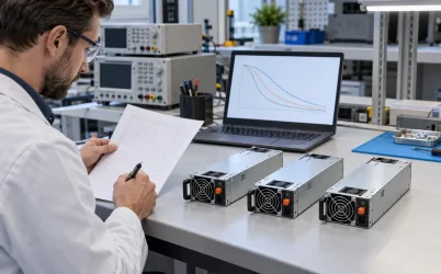
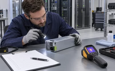
The CRPS3600T2 is a Great Wall Power Technology 3600 W Titanium-class CRPS module with a +12 V main output, +12 VSB / 3 A standby output, and a listed 185 × 73.5 × 40 mm enclosure. Its nominal rating is 400 W above the related CRPS3200T2, but that difference is useful only when the installed feed, module revision, PDB, cooling system, and surviving-module design permit it. For an existing 3200 W server, treat the 3600 T2 as an upgrade candidate, not a drop-in spare. This article shows how to decide whether the extra 12 V capacity can be safely used.
First determine what the 400 W increment represents
The two manufacturer listings place CRPS3200T2 and CRPS3600T2 in the same 185 × 73.5 × 40 mm envelope and identify both as Titanium, front-to-rear airflow, +12 V main-output products. The 3600 T2 listing gives three main current figures: 98.4 A, 229.6 A, and 295 A. The 3200 T2 listing gives four: 98.4 A, 229.5 A, 245.9 A, and 262.3 A. Their public tables do not say which input voltage, temperature, or duty condition belongs to each figure. Reading 295 A and 262.3 A as their respective highest listed points gives a difference of 32.7 A. At nominal 12 V that is about 392 W, near the 400 W nameplate difference; it is arithmetic, not an approved upgrade rating.
Even the 3600 T2’s 295 A multiplied by 12 V is 3540 W rather than exactly 3600 W. That gap is not evidence of a defect. Nominal voltage, output tolerance, standby allocation, rounding, and product rating conventions may affect the correspondence. The published summary simply does not resolve it. Request a revision-controlled datasheet that maps each current value to input bands, ambient or inlet temperature, airflow, duration, and combined main-plus-standby output. If a supplier proposes the additional 400 W as an operating benefit, ask them to identify the exact condition under which both units’ ratings are being compared.
Trace the proposed gain through the existing chassis
An upgrade claim should identify where the extra power goes. A 400 W increase on a nominal 12 V bus corresponds to roughly 33 A of additional current. If the server’s PDB, common return, protection device, module connector, or accelerator branch was qualified only for the earlier configuration, a higher-rated PSU will not raise those component limits. The added current may concentrate at a shared contact or copper transition before it reaches the intended load. Use the host manufacturer’s board and harness ratings rather than treating the PSU label as a rating for the whole server.
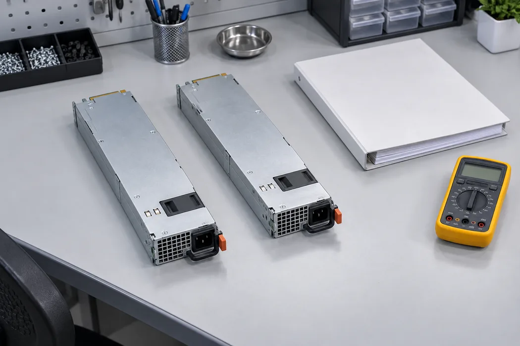
Start at the point where the module mates with the host. Confirm mechanical guides, insertion depth, latch engagement, connector position, contact assignment, and keying for the exact CRPS3600T2 revision. Equal body dimensions are helpful for screening, but they do not prove those features match. Check the main-output and return contacts, standby contacts, enable and status signals, any remote-sense wiring, and the management interface against the host’s approved module list. Neither the public manufacturer page nor the Powernexu listing publishes a complete model-specific pinout or host compatibility table, so visual similarity should not be converted into an electrical approval.
Next follow the proposed additional load. If it serves a new GPU carrier, the carrier connector and its branch protection need their own rating. If it raises CPU or accelerator limits on an existing board, the distribution region shared by those loads must be checked at the new combined current. Resistive loss scales with current squared: the effect of 33 A depends on the current already flowing and the resistance of the particular path. A thermal camera can reveal a hot region during testing, but a contact temperature limit must come from its component specification and validated measurement method.
The same reasoning applies to a replacement purchase. The CRPS3600T2 may be purchased for inventory simplification even if the server remains capped at its previous load. That can be a sound choice when the host vendor expressly supports it. It does not justify lifting the system power cap, and a technician should not infer interchangeability from the shared enclosure. Approved part numbers, revisions, and firmware requirements should appear in the service record.
Check the feed where the server actually operates
The CRPS3600T2 product page and the manufacturer listing specify 90–264 VAC or 180–320 VDC input. They do not publish a detailed power-versus-input curve in the public summary. A module accepting a voltage does not establish that its maximum nameplate output is available at that voltage. The 98.4 A, 229.6 A, and 295 A entries make it especially important to obtain the input-tier mapping before committing the system to a larger load.
Record voltage at the PSU inlet during normal operation and during the most restrictive supported condition, including transfer to an alternate rack feed. Compare the load against the manufacturer’s continuous rating at that input, not against a generic facility voltage. If a server can run from both 120 V-class and 200–240 V-class circuits, document each mode separately. A workload cap that applies only on low line must be implemented and tested, not left as a note in a purchase order. The same analysis is needed for a supported DC-fed installation, using the exact DC conditions in the technical manual.
Input infrastructure also has to support the proposed operating point. A larger output load typically means more real input power, while input current depends on efficiency, power factor, and voltage. Ask for the manufacturer’s maximum input-current and inrush specifications at the intended feed. Check the inlet, cord, PDU outlet, branch protection, and upstream allocation under the site’s electrical rules. A rack may have enough DC headroom at the module but no available AC circuit capacity for the increased server draw.
Do not treat the Titanium designation as a fixed conversion efficiency at every load. Efficiency depends on operating conditions and the applicable test program. For an upgrade decision, the useful comparison is measured or documented input power at the intended load and input voltage. That comparison tells the rack planner how much additional heat and utility power the change adds; a badge alone cannot provide that number.
Recalculate the protected load, not the sum of labels
A redundant pair presents a different question from a single-module build. If two supplies share a 3.4 kW server load and either one can fail, the surviving module must carry the full 3.4 kW under the relevant input and cooling condition. Two 3600 W nameplates do not make the protected capacity 7.2 kW. Conversely, upgrading one position while leaving a 3200 W unit in the other does not establish 3.6 kW one-failure capacity. Loss of the higher-rated module leaves the lower-rated unit and its applicable operating limit.
A mixed pair also raises an interface question. The host must explicitly support the combination, including current-sharing behavior, fault isolation, control signaling, telemetry interpretation, and service alarms. The public product table does not authorize mixed operation or specify the share method. A system might handle one unit at a different current limit, or its controller might reject the pairing. Avoid asserting either outcome without the host and module integration documents.
For an existing 3200 W redundant server, write down three loads: maximum normal draw with all modules present, demand immediately after one module is lost, and demand after any automatic power cap takes effect. Then compare each with the remaining module’s allowable rating at the worst supported feed and inlet temperature. If the platform depends on a delayed software cap, the electrical path must tolerate the interval before the cap engages. Capture that transition with representative accelerator and fan activity; a steady electronic load may miss a short excursion during failover.
Feed topology matters as well. Two PSU bays connected to one PDU may survive one module failure but not loss of that PDU. If the claimed upgrade is intended to improve service continuity, document which failure is being tolerated: a module, a cord, a PDU, or a complete upstream feed. That definition determines which surviving capacity is relevant and prevents a wattage change from being mistaken for an architecture change.
Thermal acceptance has to use the upgraded load
The manufacturer lists front-to-rear airflow and an operating-temperature range of 0–55 °C for CRPS3600T2. The public summary does not state that 3600 W is continuously available at 55 °C in every chassis or at every input voltage. A compact supply operating near its upper output tier can be limited by its own fan, server backpressure, recirculation, or a hot inlet created by neighboring equipment. The installed chassis is therefore the test environment, not merely a holder for a component test result.
For a proposed upgrade, measure PSU inlet temperature, exhaust temperature, fan state, connector region, and the PDB’s highest-current paths after thermal stabilization. Keep the other server fans and accelerator load in their intended production control modes. Test with all modules working and in the single-module state that defines protected capacity. The surviving supply can experience a higher conversion load and a changed airflow pattern after its neighbor is removed or disabled. A bay blank may be needed to preserve the designed flow; use the chassis vendor’s service configuration.
The extra electrical output is not itself the extra heat inside the PSU. Conversion loss depends on efficiency at the new operating point, while additional current can raise heating in host contacts and copper. Both effects must be measured or calculated from supported data. A thermal image is useful to locate an unexpected hot spot; thermocouples or other calibrated methods at specified points may be needed for an acceptance record. Never use a visually cool enclosure surface as proof that an internal connector is within its rating.
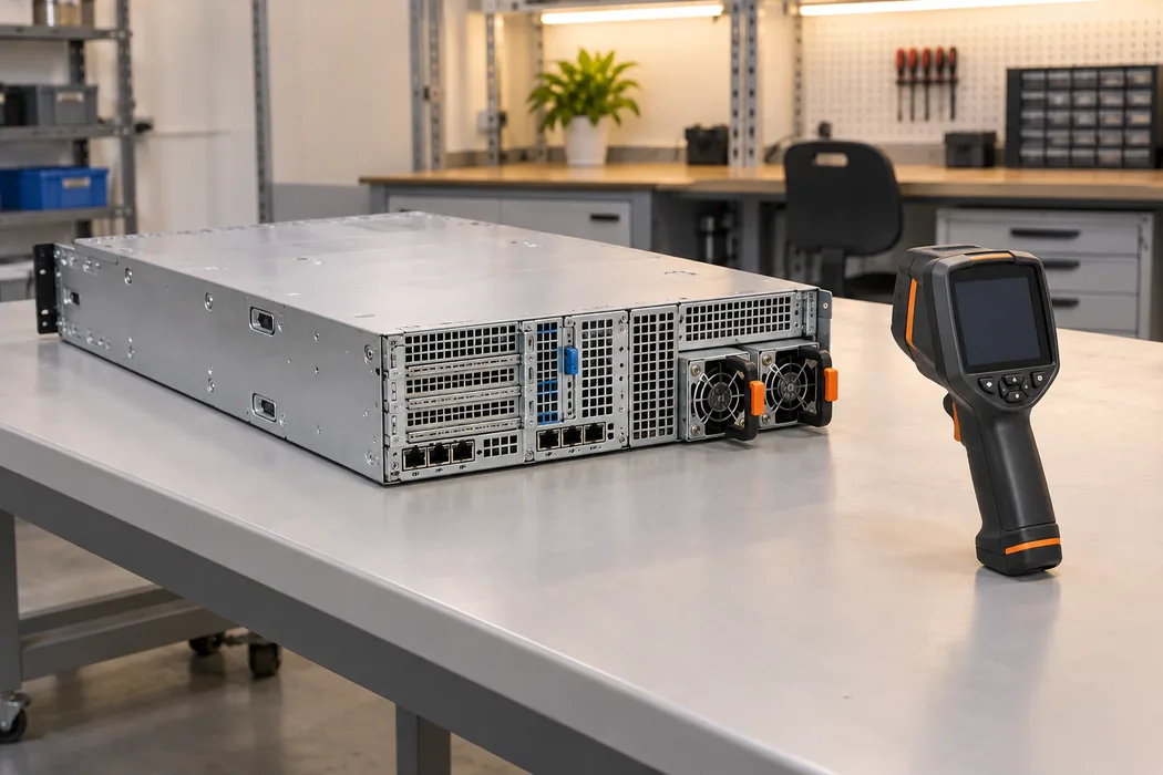
Load transitions deserve a separate pass. AI and GPU workloads can change sharply, and fans may ramp in response to the same event. Capture the voltage at a demanding downstream load and at the PSU output during the transition. A stable module output with a deep downstream dip points toward distribution impedance or branch protection; instability at the source has a different diagnostic path. Set acceptance limits from the host and component specifications before running the test, so an observed waveform is judged against a defined requirement.
Use a release record that distinguishes candidate from approved spare
An engineering release for CRPS3600T2 should join the exact model and revision to its supported host assembly, input tier, load limit, airflow direction, and service behavior. Include the module label, manufacturer datasheet, mating connector drawing, host approval, PDB rating, and test record. For a retrofit, preserve the pre-upgrade power cap and protection settings until the new configuration has passed electrical, thermal, and failure-state tests. This makes it possible to buy a higher-rated unit without accidentally authorizing a higher server workload.
Incoming inspection should compare the physical label and revision with the approved record. A supplier substitution within a similar CRPS family may preserve the nominal dimensions while changing an interface or operating envelope. If firmware reads PSU identity or reports power limits, verify that the BMC recognizes the exact unit and responds correctly to removal, faults, and a lower-capacity feed. PMBus capability or command support should be taken from model-specific documentation, not inferred from the CRPS name.
There are two defensible outcomes. If the technical manual maps the desired input condition to sufficient continuous current, the host supports the exact module, and system tests pass at the raised load and failure state, the additional capacity can be released. If any of those links is missing, CRPS3600T2 can remain a candidate or a supported same-load spare, subject to host approval. The 400 W nameplate difference is a reason to investigate; the controlled system envelope determines whether it becomes usable capacity.