G1667-4200WNA appears in Powernexu’s catalog as a 4200 W, 12 V, 185 mm CRPS module, but Gospower’s manufacturer listing for the G1667-4200W family describes a 54 V, 265 mm T265H module. Those are different electrical architectures and different bay depths. A buyer searching this exact suffix should treat the catalog record as an unresolved identity conflict, not as an approved replacement specification. The useful next step is to match the ordered suffix and revision to the module label and a manufacturer-controlled datasheet before selecting a backplane, connecting a load, or promising a 4200 W operating point.
The G1667 identity conflict changes the whole design
The Powernexu product listing reports 4200 W, 12 V at up to 350 A, 185 × 73.5 × 40 mm, and 90–264 V input. In contrast, Gospower’s G1667-4200W manufacturer page places that family in its T265H Titanium series and lists a 265 × 73.5 × 40 mm mechanical envelope, +54 V output, and 90–264 Vac input at the family level. The manufacturer’s page names G1667-4200W without the WNA suffix in its main heading; it does not publish a revision-specific WNA pinout or a complete WNA rating table in readable text. Therefore the family page is strong evidence against assuming that the Powernexu 12 V, 185 mm entry describes the same hardware, while it does not by itself settle every ordering-code detail.
That distinction is more than editorial housekeeping. A 12 V output connected to a host designed for a 54 V distribution bus would not power the intended converters. A 54 V source applied to a 12 V backplane could damage downstream electronics. A 265 mm module also needs roughly 80 mm more depth than a 185 mm one, before allowance for the connector, insertion travel, harnesses, and airflow. Similar width and height do not make the two envelopes interchangeable.
Even the arithmetic exposes the incompatible interpretations: 4200 W divided by 12 V is 350 A, the current shown in the Powernexu catalog; divided by 54 V it is approximately 77.8 A. Those are calculated ideal output-current scales, not a substitute for a controlled continuous-current rating. They imply very different busbar, contact, and board-copper designs. A purchasing team should ask the supplier to reconcile the exact suffix against the manufacturer’s label and documentation, rather than choosing the answer that better fits the existing chassis.
What the 54 V interpretation would mean inside an AI server
Gospower positions T265H as a 54 V CRPS family for heterogeneous GPU and TPU servers. In that architecture the module is a high-power source for a distribution bus; local DC converters near processors or accelerator boards create the lower voltages those devices require. A server designed around a 12 V main bus has a different conversion and distribution arrangement. The rails are not interchangeable merely because both can supply the same total wattage.
At a fixed power, the higher-voltage bus carries less current. Using the two catalog interpretations as an illustration, the 54 V path carries about 22% of the current of a 12 V path at 4200 W. For equal conductor resistance, resistive loss scales with the square of current, so a higher-voltage architecture can ease the long distribution path. Real systems also include converter losses, contact geometry, protection devices, and load transients; the lower bus current is an architectural opportunity, not proof that a particular G1667 assembly has lower total system loss.
A hypothetical 54 V bus path with 5 milliohms of combined resistance would dissipate about 30 W at 77.8 A. A hypothetical 12 V path of the same resistance at 350 A would dissipate about 613 W. That extreme comparison explains why the conductor system cannot be copied between the two interpretations. It does not describe measured G1667 hardware or an actual backplane resistance. Designers would use the real current profile, resistance of each contact and conductor, cooling arrangement, and permitted temperature rise to size the path.
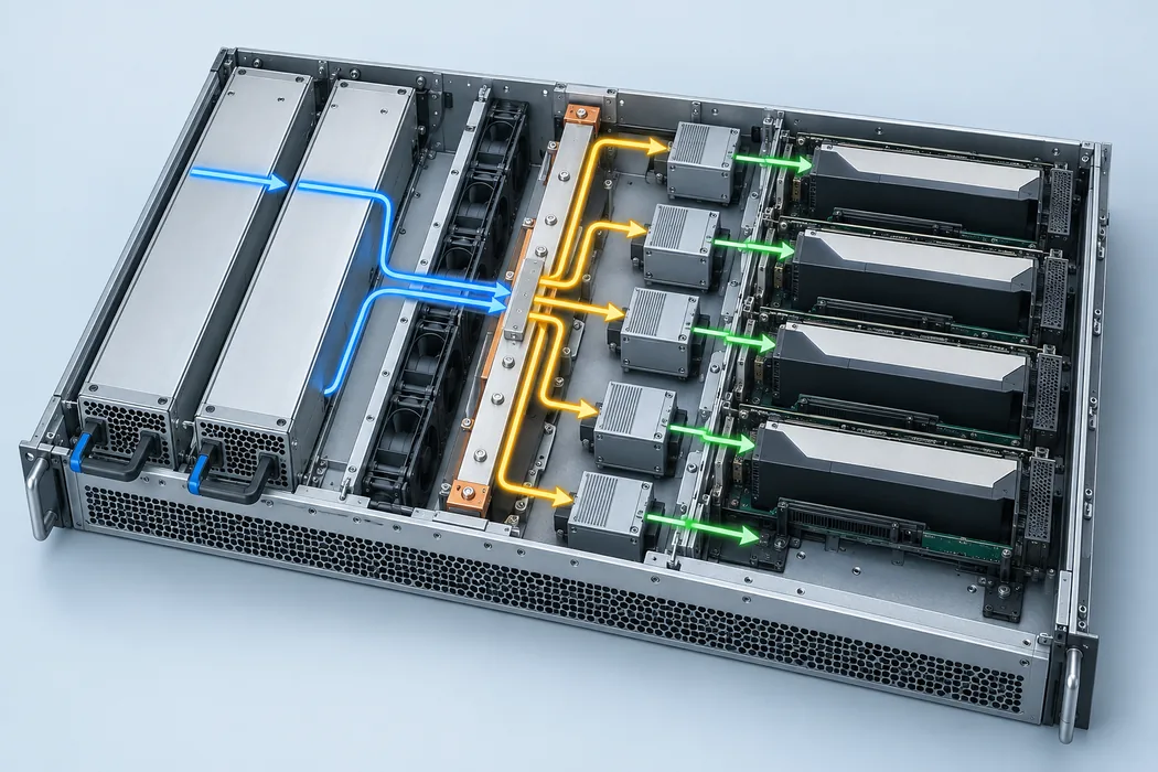
The distribution board also determines how the source reaches accelerator loads. Some boards may use a common bus and multiple local converters; others may partition power into protected zones. The public manufacturer listing does not disclose the G1667-4200WNA connector map, remote-sense pins, current-sharing signals, control pins, or standby-output behavior. A photograph of a card edge cannot establish those functions. If an AI server design expects telemetry or managed load shedding, the BMC interface must be taken from the exact approved electrical specification.
A 265 mm module is a chassis decision, not a catalog footnote
The manufacturer family envelope is 265 × 73.5 × 40 mm, while the Powernexu entry describes 185 × 73.5 × 40 mm. The 80 mm depth difference changes more than whether the module can be physically inserted. A deeper module may interfere with the fan wall, riser card, drive cage, motherboard keep-out region, or internal cabling. It may require a different guide rail and backplane location. Extraction clearance outside the rear panel can also matter in a dense rack where power cords and cable managers sit directly behind the server.
The mating plane is particularly important. A shallow bay could stop a 265 mm module before its connector reaches the backplane. A deep bay designed for a 265 mm unit might allow a shorter module to slide in without proper engagement or latching. Neither a matching CRPS label nor a similar rear handle resolves these risks. The system drawing should show the module datum, guide features, latch position, connector insertion depth, and allowable tolerances for the exact revision.
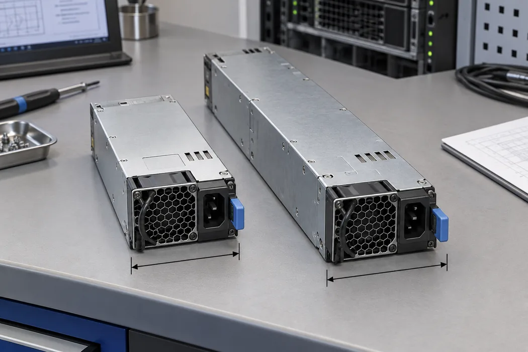
Airflow is another geometry-dependent consequence, though the public page does not give a revision-specific fan curve. The manufacturer advertises fan-reversal support for the T265H family. That is a family capability, not evidence that any WNA unit can be installed in either airflow direction without configuration or host approval. A longer body changes pressure drop and the air path through neighboring components. An existing 185 mm bay’s thermal behavior cannot be transferred to a 265 mm module by leaving open space elsewhere in the chassis.
The practical comparison begins with the removed unit, if this is a replacement project: photograph its full label, both ends, connector, latch, and installed bay. Measure the available depth from the rear panel to the backplane mating datum, not just the free-looking cavity. For a new design, reserve the manufacturer-controlled mechanical drawing as a prerequisite to board placement. The current public catalog discrepancy is too large for a fit decision based on nominal dimensions alone.
4200 W is an operating point with conditions
A 4200 W headline identifies the intended power class but does not show that full output is available at every voltage in the broad 90–264 Vac family input range. High-output server modules commonly have input-dependent limits, and the Gospower public page does not provide a readable curve mapping G1667-4200WNA output power to each input condition. A buyer operating on a 100 or 120 V branch should not infer 4200 W continuous output from a page that separately mentions 90–264 Vac and the 4200 W model name. The exact label or controlled datasheet must state the rated input, output, and environmental conditions together.
This matters for facilities planning as well as chassis design. At 4200 W DC output, the AC input must exceed 4200 W because conversion is not lossless. The branch circuit, cord, inlet, distribution unit, and protection devices must handle input current and inrush at the actual site voltage. A presumed 96% efficiency at an arbitrary load or input would create false precision; the manufacturer family page names a Titanium category but does not publish a WNA efficiency curve tied to every operating point. Use certified or manufacturer-specific test data when an energy or heat budget needs exact numbers.
For redundancy, two nominally 4200 W modules in a 1+1 host do not provide 8400 W of failure-survivable load. If one module or its feed fails, the other must carry the surviving demand within its approved rating under the actual input and temperature conditions. A host with four modules may have a different sharing and failure policy. The G1667 public listing does not establish a particular N+1 configuration, current-sharing behavior, or compatibility with a given shelf. These are host and module interface properties to specify together.
GPU load excursions add another timing dimension. A short accelerator burst can demand more current than the average workload suggests, while protective devices and local capacitors respond over different time intervals. The relevant evidence is a waveform and limits for the actual host: bus voltage at the receiving converters, PSU response, protection behavior, and any power-cap control. None of those dynamic values should be inferred from the 4200 W nameplate.
Separating the ordered suffix from the family page
Model suffixes can identify a connector, airflow, control configuration, regional variant, firmware, or project revision, but the public sources reviewed here do not define what WNA means for G1667. It would be unsafe to decode the suffix by analogy with a neighboring Gospower model. The order confirmation should explicitly identify the complete part number and hardware revision, and it should point to the datasheet, mechanical drawing, interface specification, and nameplate that apply to that build.
A useful supplier response would resolve the contradiction in one controlled document: whether the WNA order is 12 V or 54 V, whether its body is 185 or 265 mm long, and under which input conditions the 4200 W rating applies. It should also identify connector pins, permitted input type, airflow direction, standby rails, control and communication functions, and any host qualification restrictions. Those details belong in the procurement record because a later spare-parts order needs to reproduce the same functional unit, not simply the same abbreviated model family.
The label on a physical sample is a strong identity check but should not be treated as a complete integration manual. It can confirm voltage, current, input, and exact model marking if legible; it will rarely show signal timing, pin sequencing, fault response, or bus-sharing protocol. Pair the sample label with manufacturer-controlled documents, then compare both against the host’s backplane drawing. If the supplier cannot reconcile the two conflicting catalog descriptions, defer deployment in a live chassis.
Where this model fits once its identity is resolved
If the delivered G1667-4200WNA is confirmed as a member of the manufacturer’s 54 V, 265 mm T265H family, its natural engineering context is a high-density server with a matching deep CRPS bay and a 54 V distribution architecture. It may serve GPU or TPU systems with local conversion, provided the full electrical and mechanical interface is approved. A 12 V, 185 mm server bay is a different design target; no public evidence here supports treating this module as a drop-in replacement for one.
If a controlled manufacturer document instead establishes a genuine 12 V, 185 mm WNA variant, that document should supersede assumptions drawn from the broader G1667-4200W page for that exact order. The point is to let the verified ordered unit determine the system design. The public record currently contains two incompatible descriptions, and the cost of guessing is unusually high at 4200 W. Resolve the rail and depth first; then the remaining electrical, thermal, and service details can be evaluated against a coherent module identity.