HKS3600D2 is a Huntkey 54 V CRPS module advertised at 3,600 W, but its usable output changes sharply with AC input voltage. Huntkey lists 24 A at 110 Vac and 66 A at 240 Vac on the main rail. A server designer therefore cannot treat “3,600 W” as an unconditional capacity figure. The immediate questions are which line voltage reaches each module, whether the server distributes 54 V, and what capacity remains after a feed or module fails. This article reads the published ratings as operating conditions, not as interchangeable nameplate promises.
The input-voltage table is the useful specification
The HKS3600D2 product listing identifies a 54 V main output, 3,600 W rated power, 90–264 Vac input, 47–63 Hz, 240 Vdc support, and a 12 V standby output rated at 2.1 A. Huntkey’s manufacturer product page gives the more useful line-by-line current limits. The manufacturer page has a noteworthy editorial inconsistency: its heading says HKS3600D2, while the model cell inside the specification table says HKS3200D2. The heading, capacity, and published 54 V values are consistent with the Powernexu listing, but buyers should obtain a revision-specific datasheet or label confirmation before locking a bill of materials.
| Input condition on Huntkey page | Maximum listed 54 V current | Approximate 54 V output power |
|---|---|---|
| 110 Vac | 24 A | 1,296 W |
| 190 Vac | 48.2 A | 2,603 W |
| 210 Vac | 54 A | 2,916 W |
| 240 Vac | 66 A | 3,564 W |
The power column is calculated as 54 V multiplied by the stated maximum current, rounded to the nearest watt. It is an interpretation of the listed nominal output, not an additional manufacturer rating. The 3,564 W result at 240 Vac is close to the advertised 3,600 W class. At 110 Vac, the same enclosure supplies less than half that output on the published current limit. The page lists a 1 A minimum load for each 54 V row; system engineers should use the actual load range and control behavior from the approved product revision, particularly if modules enter cold standby.
Huntkey also lists 240 Vdc as a supported input, but the visible table does not assign a separate maximum 54 V current to that input. It would be unsafe to carry the 240 Vac row over to 240 Vdc without manufacturer confirmation. The same caution applies to intermediate AC voltages: do not interpolate a continuous derating curve from four discrete table entries when a threshold or firmware limit could govern capacity. For a site whose rack feeds may alternate between nominal 120 V and 208–240 V service, the lower-line case should be explicitly modeled.
A 54 V module belongs to a 54 V distribution path
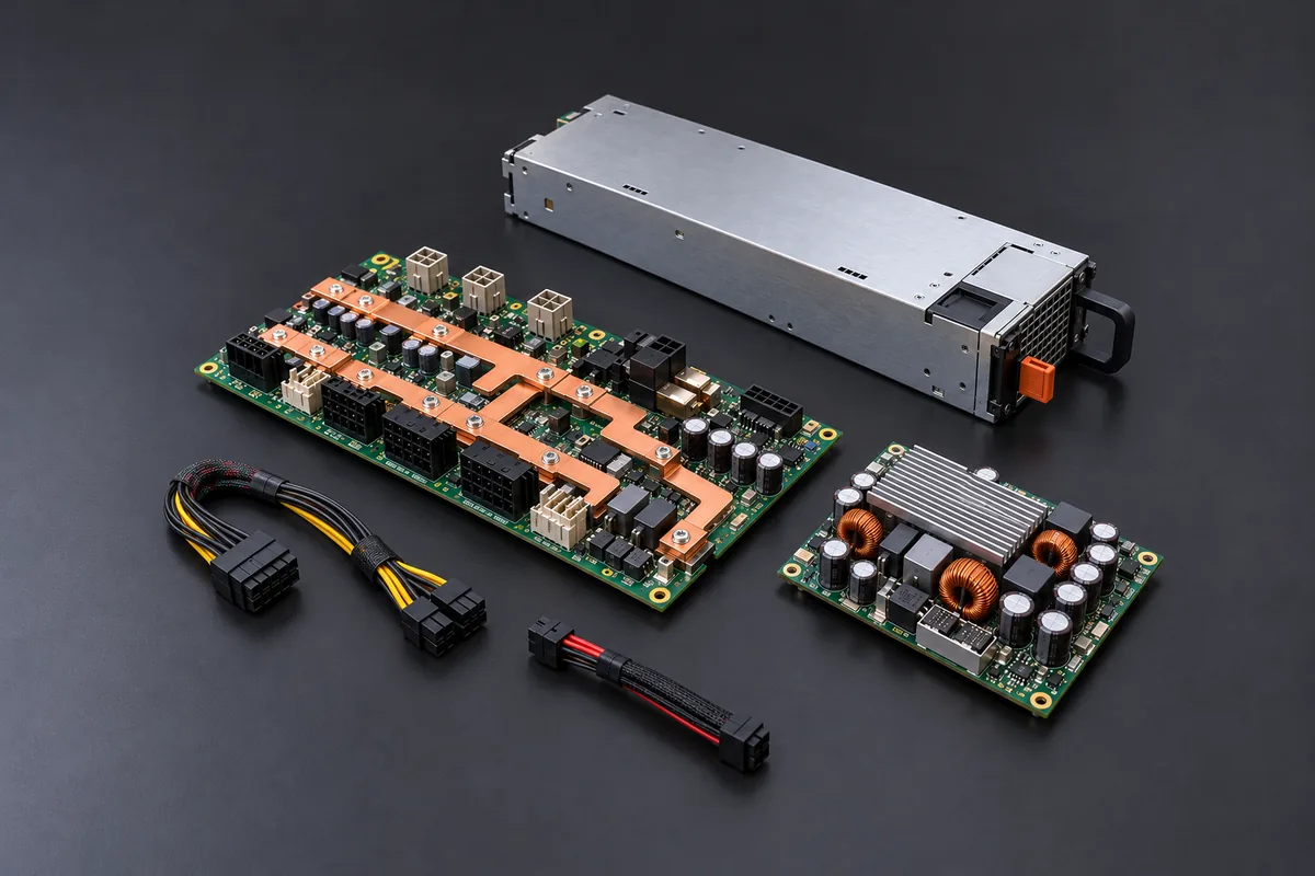
The output rail is the first architectural boundary. HKS3600D2 supplies a nominal 54 V bus, while many server power shelves distribute 12 V. Matching the external CRPS outline does not convert one bus into the other. A 12 V-only PDB or motherboard cannot accept the module as a direct electrical substitute simply because both products are removable server supplies. The connector contacts, mating sequence, sense and management signals, mechanical keying, and firmware expectations also need model-level confirmation.
In a 54 V server architecture, the higher-voltage bus commonly reaches local DC-DC converters that make the rails used by processors, accelerators, memory, storage, and control electronics. Those converter inputs, distribution traces or busbars, fuses, and connectors must tolerate the actual voltage range and transient behavior. Huntkey’s published table gives a ±8% main-output voltage tolerance and ripple-and-noise limit of 500 mVp-p. These figures describe a supply output condition; they do not establish that every downstream converter, cable, or accelerator board will operate correctly. A power tree needs the allowable input range of each downstream stage and the voltage drop between supply and load.
At 3,564 W and nominal 54 V, the listed 66 A requires a deliberate high-current path. A PDB that was laid out for a lower-power 54 V module may have insufficient copper, contact capacity, or cooling even though its nominal voltage matches. Conversely, 54 V distribution reduces current for a given delivered power compared with a 12 V bus, but that general relationship does not prove a particular 54 V assembly is compatible. Inspect the actual busbar, return path, fusing, connector temperature rise, and converter placement.
The separate 12 V standby output is not evidence of a 12 V main power bus. Its published maximum is 2.1 A; it serves low-power standby functions within the system design. Adding 12 V standby capacity to the 54 V main capacity would mix rails with different functions. The standby path also has to remain defined during module insertion, removal, AC loss, and cold-backup transitions. If the server’s management controller expects a different standby behavior or pin assignment, the power module cannot be accepted from voltage and wattage alone.
Redundancy changes which current limit matters
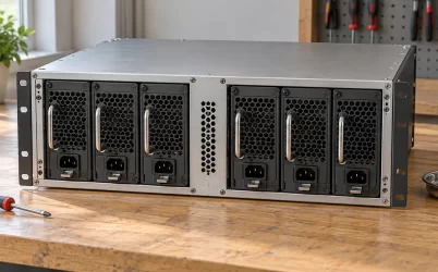
Huntkey describes N+1 redundant applications and hot swapping, with 0≤N≤3 in its product text. That feature does not mean every chassis can combine arbitrary numbers of these modules. The shelf and controller determine supported population, load sharing, fault isolation, standby state, and replacement procedure. At 240 Vac, two 66 A modules could appear to provide 132 A of aggregate nominal current in normal operation. In a 1+1 design that must survive one failed module without reducing load, the protected load still has to fit within the surviving module’s supported current and the downstream path’s limit. The same pair fed at 110 Vac would have a much lower surviving ceiling: the published 24 A row, subject to the exact system configuration.
For a three-module arrangement, the usable protected capacity depends on the number of modules required after a failure, whether all modules receive the same input voltage, and whether the backplane can distribute their combined current. A simple N+1 arithmetic example at 240 Vac might budget two surviving 66 A modules after one module failure. That is only a planning example, not a claim that a specific shelf supports 132 A or a particular current-share algorithm. The manufacturer must qualify the combination, and the server workload must remain inside its allowed voltage and thermal envelope during the transfer.
Mixed rack feeds create a subtler failure case. Suppose one input branch runs at a high-line voltage and the other at 110 Vac. A healthy pair may carry the load while the high-line module contributes most of the current. If that module or feed disappears, the 110 Vac survivor may be limited to 24 A. The relevant test is therefore not only whether the pair starts at peak load; it is whether the server can stay within the lower-line surviving capacity after the specific failure it is expected to tolerate. Workload power caps may be part of that response, but they must be validated at the platform level.
What the efficiency and cooling claims actually tell you
The Powernexu listing describes 80 PLUS Titanium and peak efficiency above 96%. Huntkey’s page labels the energy-efficiency class Titanium and lists efficiency thresholds at several load points: at least 90% at 10% load, 94% at 20%, 96% at 50%, and 91% at 100%. Its introductory sentence, however, says “Platinum” while also claiming peak efficiency above 96%. That conflicting label should be resolved with the exact certification record or manufacturer documentation if procurement requires a particular certified tier. The article’s electrical sizing does not depend on choosing either label.
Efficiency depends on the defined input voltage, temperature, and load. The published percentages should not be treated as a single fixed operating efficiency; use the relevant test curve when estimating AC input and heat at a particular workload.
That loss becomes heat in a compact 185 × 73.5 × 40 mm module and its immediate airflow path. Huntkey specifies forced-air cooling and an operating air temperature of 0–55°C. A chassis bay with blocked intake, recirculated exhaust, or insufficient fan control can overheat even if its nominal output demand is within an electrical row. The supply fan and server fan system need compatible airflow direction and enough pressure through the installed enclosure. When several modules share a tight rear bay, the failed-module or removed-module state may alter the airflow path as well as the electrical capacity.
Huntkey lists protective functions for input undervoltage and overvoltage, input current limiting, output overvoltage and overcurrent, short circuit, and overtemperature. These functions help contain faults; their trip thresholds and recovery behavior are not given in the public table. A high-current 54 V system should not rely on a generic protection label to size branch fuses or to predict whether a transient accelerator load will cause a shutdown. The approved datasheet and system test plan need the relevant thresholds, delays, and coordination details.
The published page leaves several interfaces unresolved
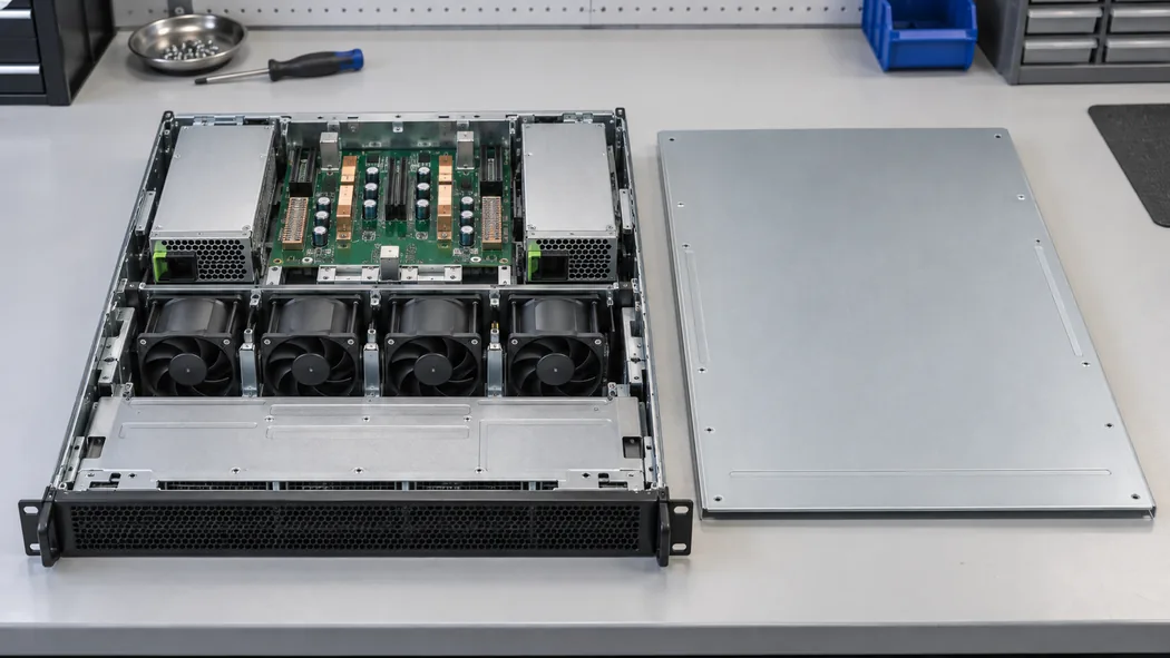
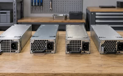
The 185 mm length, 73.5 mm width, and 40 mm height establish a starting mechanical envelope. They do not show the exact output connector, latch, handle travel, rear face, pin sequence, or allowable insertion force. The server bay must provide service clearance for a complete module and prevent the wrong electrical variant from mating. Compare the actual part and revision against the chassis drawing rather than using a family photograph as proof of fit. This is especially important when a platform has both 12 V and 54 V modules in a visually similar mechanical family.
The manufacturer page mentions cold standby, hot swap, black-box fault recording, and online firmware upgrades. It does not publish a full management command set, firmware compatibility matrix, or fault-log schema on that page. Those functions require a compatible system controller, power backplane, and service process. Before enabling firmware updates or interpreting a fault log, obtain the vendor’s approved procedure and identify the installed revision. A module that powers a bench load may still fail platform management checks if the host expects different identification or telemetry.
Hot swap requires a compatible backplane to manage contact sequencing, current transfer, inrush, and fault isolation. During a supported replacement under representative server load, watch for output droop, resets, controller alarms, and unexpected load-sharing changes.
The site lists 240 Vdc input alongside AC input. DC feed planning introduces polarity, protection, disconnection, arc behavior, and certification questions that an AC plug arrangement does not answer. A public “supports 240 Vdc” line is a reason to request the exact DC installation instructions, not a reason to assume an existing AC rack PDU or inlet is suitable. The unresolved DC output-current limit also matters if a DC feed is expected to carry the system through a source transfer.
Use the nameplate with the target rack conditions
For procurement or replacement, record the HKS3600D2 label and revision, then match its 54 V output to the host architecture. Check which input reaches each bay in normal and failure states. Use the listed current limit for each line condition rather than applying 3,600 W across the full input range. Confirm PDB, connector, airflow, management, and redundancy with the system manufacturer.
If a quote or catalog entry describes “3,600 W Titanium” without the input condition, ask for the specific operating row and the certification evidence. The conflicting model and efficiency labels on the public manufacturer page make that request particularly reasonable. A verified drawing and datasheet can settle the exact part identity, output mapping, connector, and thermal instructions before the unit is purchased as a spare.
The HKS3600D2’s distinctive planning issue is not simply its high wattage. It is a 54 V module whose published maximum current moves from 24 A at 110 Vac to 66 A at 240 Vac. The intended rack feed and the surviving module after a fault determine how much of the headline capacity a server can use. Until the host interfaces and the manufacturer-page inconsistencies are resolved, the public specification is a sound basis for screening a candidate, but not proof of drop-in interchangeability.