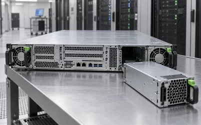
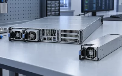
N+1 and N+N do not describe the same spare-power arrangement. In N+1, the system has the capacity needed for its load, called N, plus enough additional module capacity to survive one module failure. In N+N, two separate groups are each intended to carry the full required load. That distinction matters when a fault takes down more than one module at once: an N+1 spare may cover a single converter, while a genuinely independent second group can cover loss of the first group. Neither label, on its own, proves that the AC feeds, power distribution board, or cooling paths are independent.
First define N from the load, not from a module count
The letter N is a capacity requirement. It is the amount of working power supply needed to support the specified equipment load under the relevant input, temperature, and fault conditions. Depending on module rating and system load, N might be one module, two modules, or a larger collection. Calling a pair of modules “N+1” without saying what either module can deliver obscures the only useful question: after one fails, can the remaining capacity still carry the required load?
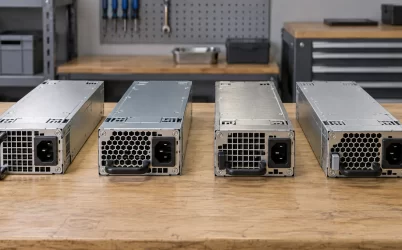
Consider an explicitly hypothetical server drawing 1,500 W at its DC distribution point and interchangeable modules that can each deliver 750 W under the stated conditions. Two modules provide 1,500 W, so N is two modules in this example. A three-module assembly can be N+1: two are required and the third is additional capacity. A four-module assembly divided into two independent two-module groups can be N+N: either group alone can theoretically carry 1,500 W. These numbers are arithmetic for illustration, not specifications for any Powernexu or third-party product. They also assume the host, backplane, controls, and thermal design actually support those populations and loads.
The common shorthand “N+1 means one extra PSU” works only after N has been established. One extra 750 W module does not make a 2,000 W load redundant in the example above. The same caution applies to a system labeled 2+2, 3+3, or 2N. The physical count suggests a topology, but the required load and surviving group rating determine whether the topology provides full-capacity redundancy.
A single failed module separates the two arrangements less than a group fault
If one converter fails in a supported N+1 assembly, the spare capacity must take the lost output without the common bus falling below what the host can tolerate. The surviving modules and distribution hardware need enough rated capacity after applicable derating. In the hypothetical three-by-750 W assembly, losing one leaves two modules and 1,500 W of nominal capacity. At exactly 1,500 W, there is no allowance in that arithmetic for an unmodeled peak, reduced rating, or current-sharing imbalance. The illustrative topology is still N+1 in module count, but actual fault-state suitability needs a realistic load envelope.
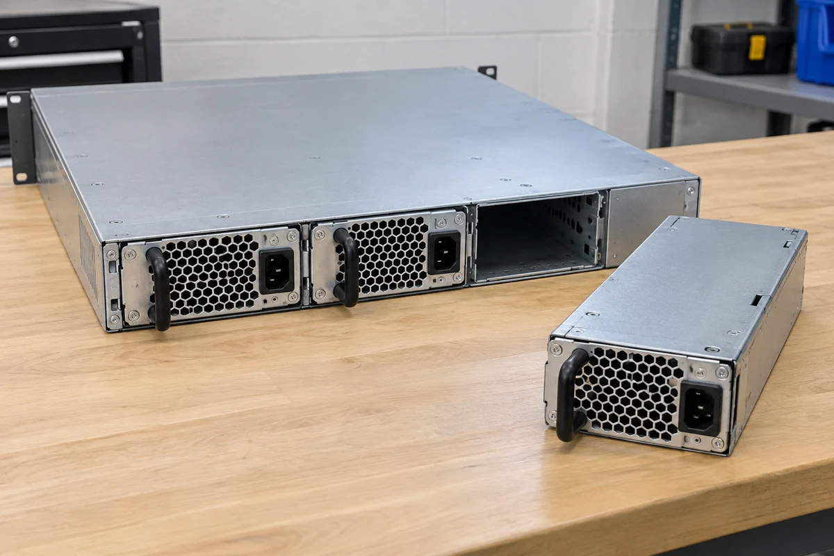
An N+N arrangement can also survive a module failure, yet its stronger claim is different. If each complete group can support the load, losing one entire group should leave the other group able to run the equipment. In the four-module illustration, a two-module group could be removed as a unit while the other two-module group retains 1,500 W nominal output. Whether the system actually behaves that way depends on how the groups connect to the load and whether failures in one group are isolated from the other. Four modules tied to one vulnerable distribution point are not automatically two independent capacity groups merely because they can be counted as two plus two.
The terminology has a real platform example. The NVIDIA DGX A100 user guide describes six power supplies arranged as a 3+3 N+N configuration and says the remaining three allow full-power operation if three supplies fail. That statement belongs to the documented DGX A100 configuration. It does not imply that every six-module server, every backplane, or every operating mode has the same surviving capacity or behavior.
A failed module is not always a neat, isolated open circuit. A fault can affect the common output bus, a connector, a hot-swap controller, a management signal, or the group feeding path. Good design isolates the fault so healthy converters are not dragged down, but the redundancy term itself does not certify that implementation. The distinction between one failed module and one failed group is useful precisely because it makes the assumed fault boundary visible.
“Independent group” is not the same as “independent building feed”
Power moves through several layers: facility distribution, UPS or PDU, AC cord, individual PSU, output-combining circuitry, distribution board, and the server loads. N+N at the PSU level concerns the converter groups and their ability to carry the required DC load. Both groups could still plug into one PDU or one UPS. In that case a PDU or upstream outage can remove both groups simultaneously. Conversely, A/B facility feeds do not make a single insufficient PSU group redundant.
Even with separate AC sources, a common output bus or power distribution board can remain a single failure domain. Two full-capacity groups need a supported means of sharing or selecting output while preventing a faulted group from pulling down the healthy one. A host designed for such a topology may provide separate input paths, controlled ORing, monitoring, and fault isolation; the exact implementation is platform-specific. Merely wiring the outputs of two supplies together without the host’s approved interface is not an N+N design.
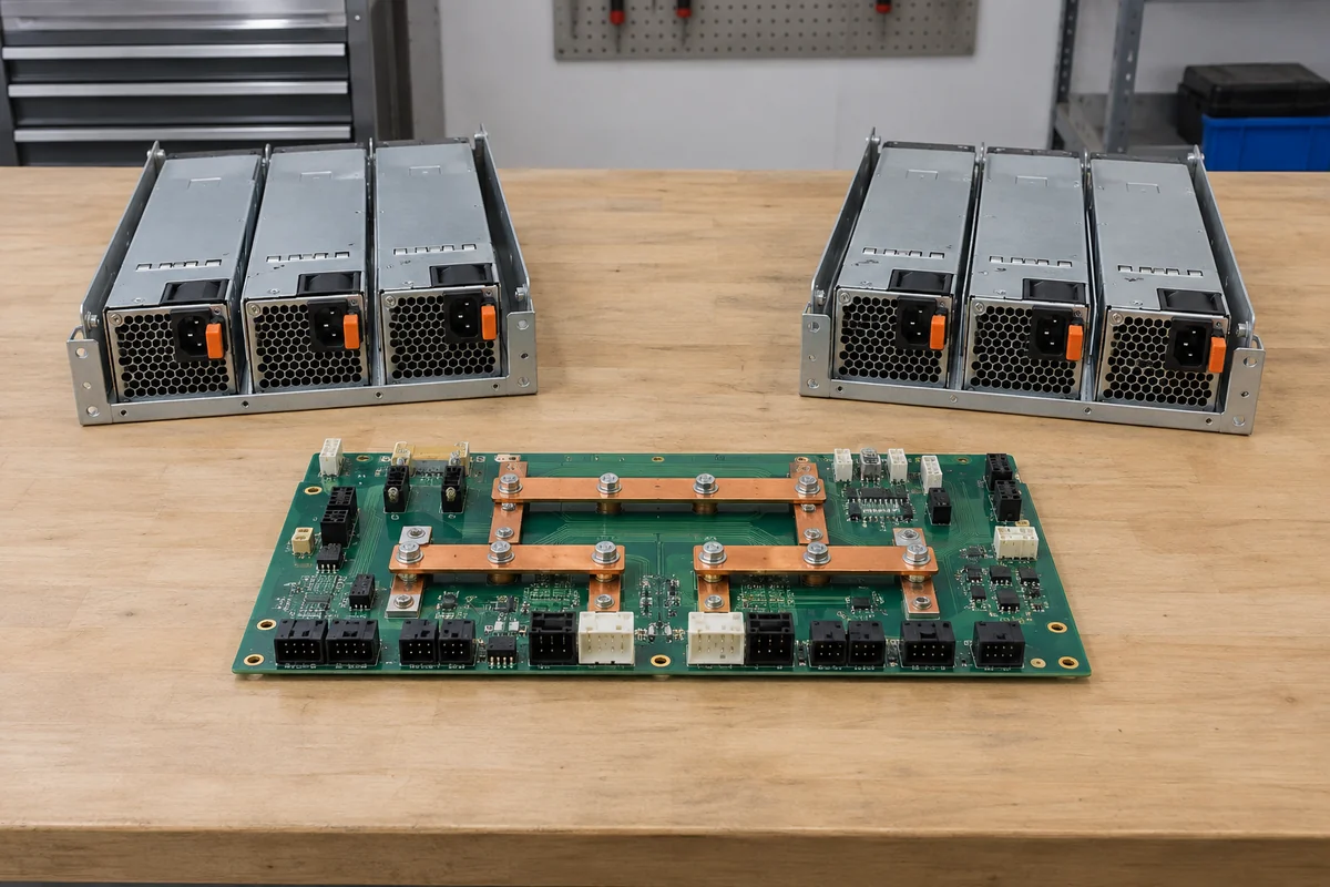
There is a useful contrast with facility terminology. A data-center electrical design may call two independently sized UPS systems “2N,” while a server maker may call its duplicated PSU groups “N+N.” Those descriptions occur at different layers. If a purchaser requires continuity after a whole upstream feed fails, the architecture must show each surviving AC-to-load path, not just repeat a redundancy label from the server datasheet. The loss of a PSU, the loss of one converter group, and the loss of one facility feed are three different tests of continuity.
A diagram that labels every group and shared component is often more informative than a count of modules. Follow each group’s inlet to its output path and identify where the paths merge. The merge point may be necessary, but it deserves attention: it can determine whether group redundancy protects the actual load or stops at the converter outputs. This is not a call to make the server entirely free of common parts, which may be impossible; it is a way to understand the protection being claimed.
Capacity after a fault is not the same as normal installed wattage
Adding the nameplate watts on every installed PSU produces a misleading comparison. In a redundant system, installed capacity includes reserve that should not be counted as extra supported workload. For the hypothetical N+1 assembly, three 750 W modules total 2,250 W of installed nominal rating, but the two surviving modules after one failure provide 1,500 W nominal. For the hypothetical N+N assembly, four modules total 3,000 W, but each independent two-module group is only 1,500 W. The protected load in both examples is 1,500 W before derating and operating margin, not 2,250 W or 3,000 W.
The difference between the arrangements therefore appears in fault granularity, not in an invitation to consume all installed capacity. N+1 reserves enough for one module, whereas N+N reserves a whole N-capacity group. The latter may use more modules and physical space for the same protected load, but it can protect against an appropriately isolated group-level loss. If the application only requires continuity after one replaceable PSU module fails, full group duplication may not buy a meaningful improvement at the failure boundary the operator actually cares about.
Input voltage and temperature matter here because a module’s available output may vary by operating condition. A rating valid at one AC range or inlet temperature should not be silently applied to another. The same applies to connector current, PDB copper, branch fusing, and airflow when the load is transferred to fewer modules. In normal operation, four modules may share a relatively modest current. After a group drops, the surviving pair and their path must carry the full load. The limiting element might be in distribution rather than in the converter nameplate.
Some hosts control load or performance when redundancy is lost. A server may continue running but cap processors or accelerators to remain inside the surviving power envelope. That is still a form of service continuity, but it is not the same as full-performance redundancy. An N+N claim worth using in a capacity plan must say whether the surviving group supports the required workload at the expected performance level, not merely whether the host stays powered.
How the modules share work changes the operating picture
The two configurations can look different in normal service even when their fault-state capacity is comparable. Modules may actively share current, run one group at lower loading, or use a manufacturer-defined energy-saving mode. These behaviors affect where conversion losses and heat appear, how quickly another module assumes current, and what a technician sees in management telemetry. None follows automatically from the N+1 or N+N name.
In a current-sharing N+1 system, all installed modules may contribute during ordinary operation. A fault then raises the current carried by each survivor. A different system may keep reserve capacity in a low-output state and change operating mode when needed. For N+N, the host may share load between full-capacity groups or use a distinct active/standby policy. Claims about efficiency, noise, or transfer time require the actual platform documentation and operating point. A generic assertion that one topology is always more efficient ignores the converter efficiency curve and control policy.
Telemetry should therefore be interpreted as an observation of the particular host, not as proof derived from the acronym. Individual PSU output, group status, input presence, fault alarms, and any power cap can show which redundancy state the system is actually in. The valuable question is whether the management view distinguishes “all modules healthy,” “one module unavailable but capacity retained,” and “one full group unavailable.” If it merely reports an undifferentiated redundancy warning, operators may not know how much fault tolerance remains.
Maintenance changes the exposure as well. Replacing a single module in an N+1 system temporarily uses the reserve that was meant to cover a failure; another failure during that service window may exceed the remaining capacity. If an N+N platform genuinely permits one whole group to be isolated while the other supports the load, work on that group may be better contained. This is conditional on the manufacturer’s hot-swap and isolation design, not a license to pull modules or energize exposed hardware without an approved procedure.
Read the redundancy label at the boundary it actually covers
N+1 is a sensible description when N modules are required and additional module capacity covers the specified single-module loss. N+N is a stronger and more expensive description when two distinguishable, full-capacity groups exist and the system can lose either group without exceeding the survivor’s supported envelope. The distinction is not whether the server contains three or four metal boxes in isolation; it is which set of boxes and paths may disappear while the required load still runs.
For a platform comparison, express the promise as a concrete event: “one PSU module can be removed,” “one power group can be isolated,” or “one upstream feed can be lost.” Then identify the surviving modules, distribution path, and workload limit for that event. Those sentences reveal when N+1 is sufficient, when N+N’s group isolation is valuable, and when neither term answers the question about the facility feed. The label becomes useful only after its capacity and failure boundary are attached to the actual system.