GW-GSP3200H-48 is Great Wall’s enclosed 3200 W AC/DC supply for a nominal 48 V output. Its published 3200 W rating provides a starting point for cabinet sizing, while the exact output-current rating needs confirmation because the manufacturer’s own datasheet contains conflicting entries. It accepts 180–264 Vac or 250–370 Vdc according to the manufacturer’s GSP3200H series datasheet. The practical question behind this model is whether a 48 V cabinet can use that power through its input source, output terminals, distribution conductors, cooling path, and load-voltage limits. It is a chassis-mounted industrial supply with stud connections, not a CRPS cartridge or a drop-in telecom rectifier module. That distinction changes the installation work even when the wattage and voltage look familiar.
What the GSP3200H datasheet establishes
The Great Wall GSP3200H series datasheet identifies separate 24 V and 48 V models. For GW-GSP3200H-48, both the datasheet and the manufacturer’s product page identify a nominal 48 V output and a 3200 W power class. The datasheet’s model-selection and detailed-specification tables give different output-current figures for this exact model, without identifying distinct test conditions or revisions. Confirm the applicable current limit with Great Wall before selecting protective devices or establishing continuous load capacity. The product family is a single-output enclosed AC/DC supply. The same document gives 180–264 Vac and 250–370 Vdc input ranges, a 278 × 177.7 × 63.5 mm mechanical envelope, fan cooling, and a 20–56 V adjustment range for the 48 V version. The unusually broad adjustment span is a published setting capability, not permission to deliver 3200 W at every set point or to connect an arbitrary 48 V load without checking its limits.
Powernexu’s GW-GSP3200H-48 product page places the supply in telecom, optical transport, network security, and centralized DC equipment. Those are plausible application categories, but the application name does not define the cabinet interface. The supply uses output stud terminals rather than a blind-mate server connector. A receiving cabinet therefore needs space for the metal enclosure, accessible and protected high-current terminations, suitable input wiring, mechanical restraint, and a clear fan-air path. Wattage and voltage alone leave these items unresolved.
The manufacturer’s document is also more useful than a broad catalog label for several operational details. It specifies an 8 ms hold-up time at 230 Vac and full load, and a full-load efficiency value of 90.5% for the 48 V version. These figures should not be extended to low-line input, high temperature, or other output settings without relevant tests. The datasheet’s operating-temperature range reaches 70°C, but available output at elevated temperature must be read against its derating information.
The source boundary: AC mains or high-voltage DC
The two published input windows describe allowable input types. The DC window starts at 250 Vdc; a nominal 48 V battery plant is far below it. Calling this a “48 V power supply” refers to its output, not its input. A site that already has a low-voltage battery bus would need a different conversion architecture if it wanted to use GW-GSP3200H-48. Conversely, a high-voltage DC distribution system may be a candidate if its full operating range, polarity, protection arrangement, and wiring match the detailed manufacturer instructions.
The AC input window begins at 180 Vac. That matters in cabinets connected to a source that can sag during generator transfer or heavy startup demand. A site that labels its feed 200 or 230 Vac should examine the lowest voltage measured at the PSU terminals while the expected load is present. The branch circuit also has to carry input power above the DC output power because conversion is not lossless. Using the specified 90.5% full-load efficiency only as an illustration, 3200 W output would imply roughly 3.54 kW at the input and about 336 W converted to heat. Actual input current and losses change with input voltage, load, and temperature.
Separate AC and DC ranges do not establish automatic transfer between two simultaneously connected sources. Nor do they reveal whether a particular host should wire only one source at a time. A cabinet requiring mains-to-DC continuity needs a documented source-selection and protection design. The 8 ms AC hold-up figure is relevant to a brief input interruption under its stated test condition; it is not a guarantee that every upstream transfer event will be bridged. Compare the actual interruption waveform and downstream load tolerance before using that number in an availability claim.
Size the 48 V distribution beyond the output studs
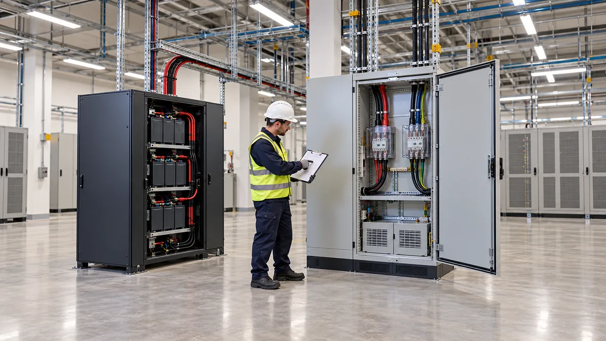
The output studs allow a bolted connection, but they do not size the downstream wire, lug, busbar, fuse, or branch distribution. Every series element in the positive and return paths adds resistance. For a measured or qualified load current I and total loop resistance R, the path voltage drop is I × R and its resistive loss is I² × R. Use the actual cable and contact resistance, the cabinet’s load profile, and a manufacturer-confirmed output-current limit when applying these equations. Do not derive a protective-device rating from the contradictory current entries in the published datasheet.
Voltage at the supply terminals is not necessarily voltage at the electronics. A shelf specified to work within a particular input range sees the voltage after busbar, connector, protective-device, and harness losses. If the PSU is set near 48 V and a load’s minimum permissible input is close to that figure, a long or warm distribution path may use the remaining margin. Raising the supply setting is not an automatic cure: other branches might then see too high a voltage at light load, and the 20–56 V adjustment capability is broader than many downstream device ratings. Define minimum and maximum voltage at every receiving terminal before selecting a set point.
Remote sensing, where implemented according to the manufacturer’s interface instructions, can compensate for some distribution drop by regulating at a selected sense location. It cannot restore power lost as heat in an undersized contact, and it does not make all branches equally regulated. The location of the sense pair matters: the supply may hold one bus point steady while a distant branch still sees a different voltage. An open or miswired sense lead can also create an undesirable control condition. The controlled wiring diagram and failure behavior should be available before the feature is relied upon.
The nominal 48 V rail may feed DC/DC converters rather than final electronics directly. In that case the input power of each converter, including its losses and startup demand, belongs in the PSU load estimate. For example, a converter delivering 600 W at an assumed 90% efficiency draws about 667 W from the 48 V bus in that example operating state. Several such converters can create a bus load above the sum of their output ratings. The input capacitors of those converters may also demand a short charging pulse that an average-power calculation does not represent.
Matching an enclosed supply to a telecom cabinet
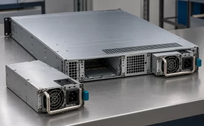
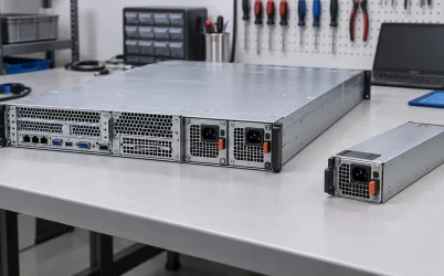
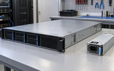
The 278 × 177.7 × 63.5 mm enclosure is a starting dimension, not a complete installation envelope. The mounted assembly also needs room for cable bend radius, lug insulation, access to fasteners, the inlet and exhaust paths, and whatever guard is required around power terminals. A cabinet drawing should show the unit in its installed orientation with those working spaces included. Simply finding a rectangular empty volume of the same dimensions is not sufficient to demonstrate that the supply can be serviced or cooled there.
The built-in fan makes the airflow path part of the electrical rating. Restricting an inlet, exhausting into a closed pocket, or recirculating air from another hot assembly can raise component temperatures even while room ambient remains within a published range. A telecom cabinet may have its own fans and baffles; their pressure direction should cooperate with the PSU fan rather than oppose it. Place temperature measurements near the actual PSU inlet and outlet under the cabinet’s worst expected operating configuration. Room-temperature data alone may miss a local hot spot.
The manufacturer’s high-temperature operating limit must be interpreted alongside output derating. A cabinet intended for full 3200 W in a hot outdoor enclosure has a different burden from an indoor rack that normally operates at half load. At altitude, lower air density may also reduce cooling margin; a published altitude capability does not automatically preserve full power under every combination of load and temperature. The realistic operating point is the intersection of input voltage, load, output setting, cabinet airflow, ambient temperature, and any manufacturer derating rule.
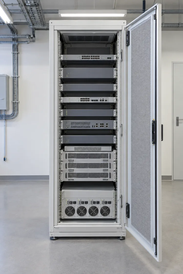
For a network-security appliance or optical transport shelf, service access can be decisive. The supply is not a rear-extractable hot-swap module by virtue of serving telecom equipment. Replacing a bolted, chassis-mounted unit may require isolation, access to input wiring, output-lug removal, and cabinet downtime. If uninterrupted module replacement is a system requirement, the shelf and power modules must be designed for it. The GSP3200H’s enclosed form supports a different mechanical approach.
Parallel capacity is a system function
Great Wall states that up to four identical GSP3200H units may operate with current sharing. That is useful for a power shelf needing more capacity, but four nameplates do not establish usable cabinet power without the prescribed sharing wiring, distribution design, and operating limits. The modules need an approved current-sharing interface and balanced output paths. Unequal conductor resistance can cause one unit to carry more current even when all four have the same nominal voltage setting.
Parallel operation and redundancy answer different questions. Two 3200 W units sharing a 5 kW load provide combined capacity while both are running, but one surviving unit cannot sustain the full load after the other is lost. A 1+1 arrangement whose surviving unit can carry the whole load has a different usable-capacity limit, subject to real derating at that site’s temperature and input conditions. Bus isolation, fault containment, upstream feed separation, and replacement method are cabinet responsibilities. The published four-unit sharing allowance does not specify those features for every host.
The auxiliary 12 V output and remote-control signals can support a managed installation, but they should be assigned only from the manufacturer connector documentation. A system integrator should not infer a PMBus map, backplane pinout, or plug-in sequencing from the presence of control functions. If a controller is expected to detect PSU faults, define what each available status signal actually represents and how the cabinet reacts when the primary 48 V rail is lost or a fan reports trouble.
Interpreting the model for a real 48 V load
GW-GSP3200H-48 is a strong catalog candidate when a cabinet needs a high-current, adjustable 48 V source and can accommodate a fixed enclosed supply with bolted output connections. Its published data support a 3200 W class output, specific AC and high-voltage DC input windows, fan cooling, and a path to parallel operation. The most consequential engineering work is at the boundary between the PSU and its host: source behavior, high-current distribution, load voltage at the terminals, heat removal, and service method.
A useful application inquiry starts with the exact load-voltage window and measured or calculated current profile, then adds the lowest and highest input voltage the site can present. Draw the positive and return distribution paths, including protection and connections, and account for voltage loss at maximum current. Place the supply and terminations in a mechanical view that leaves cooling and maintenance access. For parallel designs, state both the normal combined load and the load that must survive a unit outage. These details let a vendor assess the model against a real cabinet rather than a nominal wattage alone.
The designation also prevents a common category error. This is not a 48 V battery-input unit merely because it produces 48 V, and it is not a standard server CRPS merely because it can support communications equipment. Its documented output and enclosed construction make sense where a cabinet can be designed around an industrial AC/DC converter. Where the host instead requires a specific hot-swap rectifier bay, low-voltage DC input, or blind-mate server interface, the required architecture points to a different product class.