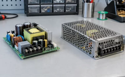
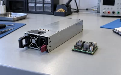
A server PSU output described as a 2×25 card edge has a recognizable connector type, but that description does not identify an exact receiving component to order. The missing link is the manufacturer’s reference connecting the PSU interface to a particular connector, drawing, and assembly. Even a printed component number can describe a reference configuration rather than an approved replacement.
For server power supply DC output connector types, the practical distinction is between identifying the physical interface and establishing its mating-part identity. Three legacy Intel specifications illustrate that distinction unusually well: they describe related card-edge arrangements while preserving different connector references. Reading those references in their original sections reveals what is documented, where the descriptions diverge, and which procurement questions remain unanswered. These examples concern the named historical platforms; they establish no current component availability or universal CRPS interchangeability.
Connector names identify different levels of hardware
Card edge, cable connector, and busbar contact describe physical arrangements at different output boundaries. A removable module can present a board edge to a fixed receptacle. A cabled output can require a housing, terminals, and a manufactured harness. A busbar interface can belong to a larger distribution assembly. Recognizing the arrangement helps locate the relevant documentation, but does not finish the component description.
The Intel examples here concern the module’s DC card edge and its receiving connector. They do not identify an AC inlet cord or a downstream CPU power lead. Keeping that boundary narrow prevents a familiar motherboard connector name from being substituted for the receptacle hidden inside a PSU bay.
Within that boundary, three descriptions carry different information. A family name identifies a category. A configuration reference associates the interface with a named component’s arrangement. An ordering identity specifies the component actually supplied. A document can provide the first two without establishing the third.
The phrase “compatible with” also needs its object. Compatibility with a stated pin configuration describes a narrower relationship than approval of a complete replacement assembly. The surrounding sentence matters: retain whether the manufacturer refers to contact configuration, mechanical engagement, or system support instead of shortening all three to “compatible connector.”
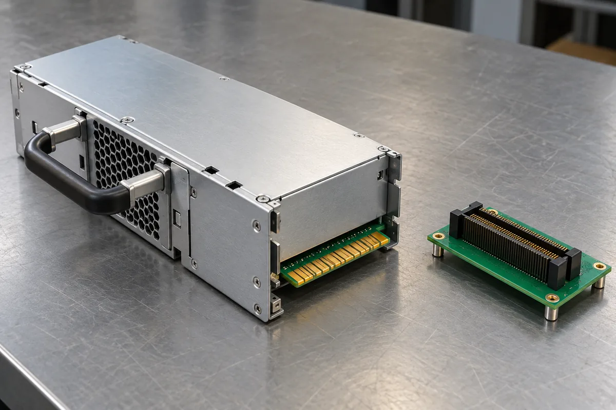
S2600GZ/GL names a reference configuration
Intel’s S2600GZ/GL Technical Product Specification, revision 2.4, places its connector description in section 11, Power Supply Specification Guidelines. The section explicitly characterizes its power-supply data as reference information reflecting requirements for a 750W supply used in an Intel-designed 2U platform. That scope travels with the connector passage.
Section 11.1 describes two main power slot connectors on the server board. It calls for a PSU card-edge output carrying power and signals, compatible with a 2×25 power card-edge connector. The passage references the pin configuration of FCI 10035388-102LF as equivalent. Table 53 then provides the platform’s output contact assignments.
This establishes more than a visual resemblance: there is a named interface configuration and a documented contact table. It gives an engineer a concrete component reference to investigate. However, the wording does not identify a currently available purchasing option, establish an approved alternate, or provide the connector manufacturer’s complete component drawing.
Consider a hypothetical supplier response offering a “2×25 server PSU socket.” The Intel passage permits a more precise question: which documented relationship connects that offered socket to the referenced 10035388-102LF configuration? A matching position count answers only part of that question. The supplier’s exact component identity and applicable drawing remain necessary to explain what is actually being offered.
The document revision and the component suffix identify different things. Revision 2.4 identifies Intel’s specification; the LF characters belong to the component reference reproduced within it. A supplier’s newer catalog date does not itself amend Intel’s interface requirement. Likewise, finding the same base number in an older catalog does not explain the complete referenced identity. The missing relationship needs an explicit documentary basis.
The reference is useful even before that answer arrives. It moves the investigation from an anonymous socket toward a named configuration. Its limitation is equally specific: the platform document supplies an interface reference, while the offered component still lacks a demonstrated connection to it.
P4304 preserves separate -102, -102LF, and -106 references
The Intel Server Chassis P4304XXMFEN2 / P4304XXMUXX Technical Product Specification, revision 1.2, makes the distinction sharper. Its optional 750W supply section contains both an outline drawing and connector text. Figure 19 labels the connector reference 10035388-102. The adjacent section 2.2.1.1 names the equivalent 2×25 pin configuration of 10035388-102LF.
The separate optional 1600W supply section has its own mechanical overview. Figure 23 carries a 10035388-106 reference. These entries should remain attached to their respective figures and sections. The document’s shared chassis title does not merge them into one interchangeable purchasing identity.
The following comparison records the references without treating them as approved alternatives. The source is Intel’s P4304 chassis specification, revision 1.2.
| Document location | Reference preserved | What the passage supplies |
|---|---|---|
| 750W Figure 19 | 10035388-102 | A connector reference on that supply’s outline drawing |
| 750W section 2.2.1.1 | 10035388-102LF | An equivalent pin-configuration reference |
| 1600W Figure 23 | 10035388-106 | A separate connector reference on the 1600W outline |
| PDB section 2.4.2.1 | 10035388-102LF | A receiving-interface configuration with additional mechanical context |
The difference between -102 and -102LF in the 750W material remains unresolved by these passages. It would be premature to declare the suffix insignificant, infer its meaning, or silently replace one spelling with the other. Connector-manufacturer documentation connecting those identities would be needed to support that interpretation.
The -106 reference appears in a different supply section. That is a distinct documentary observation, rather than proof of an error in the 750W section. Equally, its appearance does not establish that -106 replaces -102LF. Each reference can be recorded accurately without inventing a substitution relationship.
Keep the original figure caption with any extracted reference. A detached screenshot of the -106 label can lose the fact that it comes from the 1600W outline. A text-only search can lose the -102 label while retaining the nearby -102LF sentence. Neither excerpt becomes a complete account of the document simply because it is easier to search. The figure and adjacent prose need to remain associated in the investigation.
For a buyer investigating the 750W interface, the useful result is therefore a paired reference: Figure 19 uses -102, while its adjacent text uses -102LF. For an investigation of the 1600W outline, the relevant drawing reference is -106. Preserving those contexts avoids selecting whichever number produces the easiest search result.
The PDB passage makes sheet-metal keying part of the question
Section 2.4.2.1 of the same P4304 document describes the power distribution mating connector using the 10035388-102LF pin-configuration reference. It also adds details absent from a simple connector-type label: the described version raises the card edge by 0.031 inch to accommodate future 0.093-inch PCBs, and the connector itself has no keying features. In that described arrangement, system sheet metal provides the keying.
These are platform-specific statements. The stated dimensions should not become a general thickness rule for server PSU edges, nor should the absence of connector keying be generalized to unrelated card-edge products. Their value is explaining why the receiving component’s installed geometry cannot be reconstructed from its contact count.
A socket can belong to the intended interface configuration while its location on a newly designed board remains wrong. The board mounting position, connector height, and chassis guidance determine where the module edge arrives. Here, the source explicitly assigns keying to surrounding metalwork, so a loose connector does not reproduce the documented mechanical arrangement by itself.
This changes the component question. For a bare receptacle purchase, the missing information includes its applicable mounting and mating drawing. For a replacement PDB purchase, the offered board assembly must preserve the relevant installed relationship. Those are different purchasing scopes even when both quotations mention the same connector reference.
The raised-edge statement also explains why an outline and a contact table answer different questions. The table identifies electrical positions; the mechanical passage describes where mating occurs in the installed arrangement. Neither substitutes for the other. The practical information supplied by the PDB passage is the dependency: connector configuration and chassis keying work together in this particular arrangement.
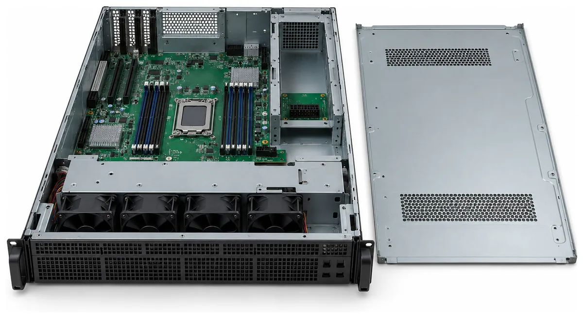
H2000WP gives -106 another platform context
Intel’s H2000WP Family Technical Product Specification, revision 1.6, provides a useful comparison because its Figure 11 also carries a 10035388-106 reference. Section 3 describes support for 1200W and 1600W modules and a custom power connector board serving four S2600WP nodes. Section 3.1.5 and Table 10 supply the PSU output contact map.
The repeated -106 reference is a worthwhile discovery lead. It connects the investigation to another documented platform passage. It does not establish that the H2000WP receiving assembly can replace the P4304 assembly, or that either system accepts every supply associated with that reference elsewhere.
The custom board matters to interpretation. A connector component and a receiving board are different manufactured objects. A shared component reference, even if subsequently confirmed, would leave the board’s mounting, routing, and platform relationships unresolved. Purchasing the board involves an assembly identity beyond the connector number shown in the PSU outline.
The two documents also describe different scopes. P4304 separates optional supply sections within a chassis specification. H2000WP places its connector discussion inside a multi-node system power subsystem. Combining their references into a universal connector chart would remove precisely the context needed to understand the receiving hardware.
Nor does repetition make the two platform documents a connector manufacturer’s approval statement. Both are evidence of how Intel described particular system interfaces. Resolving a component-level alternative still requires documentation addressing the proposed component relationship itself. This distinction prevents two matching historical references from being counted as independent confirmation of a substitution neither document actually states.
Read together, the documents establish that -106 appears in both cited outlines. They do not establish a cross-platform bill of materials. A proposed common receiving component therefore needs its own supporting component documentation, while any claimed assembly interchangeability needs evidence for the specific platforms involved.
A mating-part answer must preserve the unresolved relationship
A useful answer to a supplier can now name the exact documentary gap. For the P4304 750W case, identify revision 1.2, Figure 19’s -102 reference, and section 2.2.1.1’s -102LF configuration reference together. Ask which complete manufacturer ordering identity is proposed and which component drawing explains its relationship to those references. This requests resolution of an actual discrepancy rather than another generic compatibility assurance.
If the offer instead concerns the 1600W arrangement, identify Figure 23 and its -106 reference. If it concerns H2000WP, identify revision 1.6 and Figure 11 separately. Evidence supplied for one of these questions should not silently close the others merely because each involves a 2×25 card edge.
A quotation for a bare connector should distinguish that component from a populated PDB, a complete power cage, or a module-and-receiver kit. Conversely, a service replacement identified by the platform manufacturer may be ordered as an assembly without the buyer reconstructing every internal component identity. The ordering scope determines which unresolved reference actually affects the purchase.
For these Intel examples, the documented outcome is a set of precisely located connector references and a receiving-side mechanical dependency. The remaining gap is the supported relationship between those references and the actual offered part. Until that relationship is established, 10035388-102, 10035388-102LF, and 10035388-106 remain separate references in their cited contexts. None is presented here as an approved purchasable mate or substitute.