A fault in data center DC power distribution can draw energy from a converter and from storage already connected to the distribution circuit. Opening one protective device removes the contributions whose paths cross that device, provided it successfully interrupts them. Charged components on the fault side can remain connected. The useful engineering question is therefore where the energy resides, how it reaches one specified fault, and which paths disappear as protection operates.
DC distribution is an architectural alternative to conventional AC delivery, as ABB’s data center overview describes. Its fault behavior requires a more detailed circuit description than that architectural label supplies. The following hypothetical rack branch illustrates the energy account without assigning a fault-current rating, clearing time, or protection capability to any commercial equipment.
Fix the fault on one side of the branch interrupter
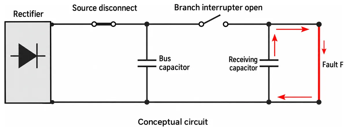
Consider a conceptual rectifier supplying a two-conductor DC bus through a source disconnect. A bus capacitor connects across the distribution conductors after that disconnect. One rack branch leaves the bus through a branch interrupter and feeds a receiving assembly containing an input capacitor. Place fault F across the branch’s outgoing and return conductors, downstream of the branch interrupter and at the receiving assembly’s input node.
For this example, assume those connections are direct conductive paths while the devices are closed. No battery, second feed, or reverse-blocking component is included. Both capacitors begin charged. These are stipulated circuit conditions, not a reconstruction of a server rack or a recommended installation.
The position of F determines the initial path tracing. Rectifier delivery reaches F through the source disconnect and branch interrupter. Bus-capacitor discharge reaches F through the branch interrupter but bypasses the source disconnect. Receiving-capacitor discharge reaches F locally, without passing through either upstream device. Each loop includes the associated return conductor; a single arrow from a source to F would conceal half the circuit.
A pole-to-earth fault is a different case. Its path depends on the actual bonding arrangement, insulation, and connections to earth. The two-conductor fault assumed here provides no basis for predicting earth-fault current or prescribing which conductors an installation must switch.
This topology already exposes a useful distinction. A source-disconnect current sensor cannot observe a capacitor-discharge loop that bypasses its location. Likewise, the branch device sees upstream contributions crossing its position, but not the local receiving capacitor’s entire discharge. Measurement location and interruption location belong on the same circuit drawing.
The first contribution can already be inside the rack
A charged capacitor stores electrical energy. For an ideal capacitance C at voltage V, stored energy is E = ½CV². Between an initial voltage and a later voltage, the decrease is ½C multiplied by the difference between their squared voltages. That relationship identifies an energy reservoir; it does not predict the discharge peak or where the released energy is dissipated.
In the conceptual branch, the receiving capacitor has a local route to F. Its initial contribution does not need the rectifier to increase its output. Source current limiting therefore does not, by itself, bound this local discharge. The loop’s resistance and inductance, capacitor characteristics, connection geometry, and evolving fault impedance influence the waveform.
The bus capacitor has another route. Its discharge crosses the branch interrupter before reaching F. While that path remains conductive, it can contribute even if the source disconnect has already interrupted rectifier delivery. Treating every capacitor as part of the source would hide this distinction and could assign its energy to the wrong protective device.
Actual converter capacitance needs more careful placement. A capacitor directly connected across the documented output terminals differs from an internal reservoir separated by switching stages, a transformer, or blocking circuitry. The latter’s stored energy cannot simply be added to the fault account as though a wire connected it to F. Its accessibility depends on the converter implementation and fault state.
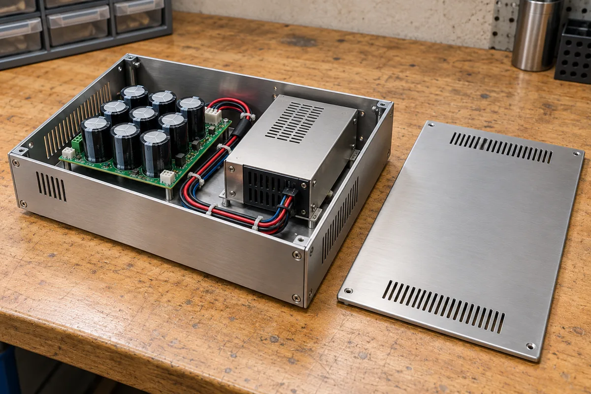
Capacitance also needs its applicable operating value and voltage. A component’s nominal marking alone may not describe effective installed capacitance under bias, tolerance, and temperature. Without those data, the example supports a qualitative contribution map, not a numerical energy budget.
Inductive storage adds another consideration. An ideal inductance carrying current stores ½LI². When switching changes its current path, that energy must transfer through the remaining circuit, dissipate, or enter an intentional absorption network. It should not be counted twice as both initial storage and newly supplied energy.
The converter responds while stored energy is moving
Capacitor discharge, converter control, and protection response can overlap. A drawing divided into initial discharge, current limiting, and interruption is useful for explanation, but it should not imply three clean, nonoverlapping intervals. Their actual timing requires applicable component behavior and the installed circuit.
The rectifier’s rated output current describes a supported operating condition. It does not establish its instantaneous contribution to F. A manufacturer may document current limiting, shutdown, intermittent restart, or another response for a particular converter. Those descriptions need their conditions and timing before they can be used in this branch’s fault model.
For example, a documented regulated current limit could bound one part of source delivery after its control responds. It would not retroactively limit energy already discharged through an external capacitor. A documented shutdown could stop controlled power conversion while leaving an output capacitor connected. Whether another conductive path remains through the converter is a separate circuit question.
A restart function changes the observation interval. If an implementation reconnects energy while F persists, the account must include the subsequent delivery. A single initial pulse would then describe only part of the event. Conversely, an assumed retry sequence should not be assigned to equipment whose recovery behavior is unknown.
A battery requires its own contribution path if one is actually present. Direct connection through distribution impedance, connection through a controlled converter, and disconnection by battery protection produce different possibilities. Battery capacity alone cannot establish current at F. Adding a battery symbol without its intervening equipment would make the energy drawing less informative.
The source contribution therefore remains a time-dependent quantity. Its applicable model must describe delivery before and during protective action, including any continuing or renewed supply. An overload percentage or a feature acronym is insufficient to supply that history.
Opening the branch removes some paths and leaves another
Now assume the branch interrupter successfully interrupts every path assigned to it in the conceptual circuit. Upstream rectifier delivery and bus-capacitor discharge can no longer reach F through that branch connection. The receiving capacitor remains directly across F because its discharge loop lies downstream of the interruption.
Compare that result with opening only the source disconnect. Rectifier delivery through the disconnected source path stops, but the bus capacitor remains connected to F through the still-conducting branch device. The receiving capacitor also retains its local path. These two actions remove different contributions even though both might be described loosely as switching off the supply.
The phrase successfully interrupts carries a technical condition. A trip command, detected threshold, or mechanical motion does not by itself establish the end of current through the device. The applicable DC interrupting capability and circuit conditions must cover the duty. For an electronic switch, its off-state behavior, current direction, voltage stress, and energy-handling provisions also matter.
An off command should not be interpreted as a universal physical isolation boundary. Leakage, semiconductor paths, auxiliary connections, or a separately connected source can matter in an actual assembly. Each requires documented treatment where it affects the conclusion; none is an assumed feature of this example.
Likewise, the branch interrupter’s successful action does not establish how much energy was delivered before interruption. Detection delay, control response, current decay, and any absorption process contribute to that question. Use a common timing reference when comparing those events. Otherwise, a short advertised switching interval can be mistaken for the entire fault duration.
After interruption, redraw the surviving loops rather than merely changing a device symbol to open. In this example, the local capacitor loop survives. If a real receiving assembly includes a blocking element between its capacitance and F, that loop may differ. The drawing must follow the installed circuit rather than inherit the example’s direct connection.
Stored joules do not identify where damage occurs
An energy inventory and a damage prediction answer different questions. The inventory identifies what can release or continue supplying energy. Damage depends on where that energy is deposited, the associated current and voltage, exposure duration, and the affected materials and components.
For a defined element, electrical energy transfer can be evaluated by integrating its instantaneous voltage multiplied by its current over the relevant interval. Voltage and current must refer to the same element and timebase. Multiplying an unrelated peak voltage by peak current and an assumed duration does not reconstruct the event.
An ideal zero-resistance short illustrates the boundary problem. Its ideal voltage is zero, while substantial current can still produce heating in the real conductors, contacts, and source impedances surrounding it. Calling all released capacitor energy energy at the fault would obscure those deposition locations. A real arc introduces another voltage-current relationship that needs its own applicable model.
For a resistive conductor, integrating I²R describes heating under the model’s conditions. Resistance can change during the event, and conductor temperature depends on more than the electrical integral. A protective device’s published let-through data also have defined test conditions. Neither relationship authorizes transferring one component’s withstand result to another.
Two capacitor banks with equal initial stored energy can consequently impose different stresses. Different loop impedances can change peak current and duration, while different physical routes expose different joints. Conversely, a smaller reservoir located close to a vulnerable connection can matter more to that connection than a larger reservoir whose contribution is interrupted elsewhere.
A qualitative topology can establish those distinctions before numerical modeling is possible. It cannot establish a clearing rating, acceptable connector exposure, arc-flash result, or personnel protection conclusion without the corresponding equipment and assessment evidence.
Moving capacitance changes what the interrupter can contain
Return to the receiving capacitor beside F. Suppose a second conceptual arrangement places that same capacitance on the upstream side of the branch interrupter, while preserving its initial voltage. Its initial stored energy is unchanged. Its route to F now crosses the branch interrupter, so successful interruption can remove that contribution along with rectifier delivery.
This does not make upstream placement universally preferable. Local capacitance may serve the receiving converter’s transient demand or another documented electrical requirement. Moving it changes wiring relationships and potentially the receiving circuit’s behavior. The comparison demonstrates a protection consequence, not permission to relocate components in commercial hardware.
Keeping capacitance downstream creates a different engineering obligation: account for the local discharge where an upstream device cannot interrupt it. Possible design responses depend on the receiving assembly and its supported circuitry. A larger upstream breaker does not change which side of that breaker contains the reservoir.
For the original hypothetical fault, the supported qualitative result is precise. Rectifier delivery crosses both devices, bus-capacitor discharge crosses the branch device, and receiving-capacitor discharge crosses neither. The actual waveforms and component exposures remain unassigned. That distinction explains where fault energy comes from while preserving the difference between tracing a possible path and proving an installed protection outcome.