The G1358-2000WNA is a 2000 W, 12 V class hot-plug CRPS listed by Powernexu for server and networking equipment. There is an important ordering detail: Gospower’s current public product page names G1358-2000WNAA, with two final A characters, and describes a +12.2 V T185 Titanium module. The two suffixes may represent a revision, regional order code, or different hardware; the public pages do not establish equivalence. A replacement purchase should therefore begin with the complete label and a controlled manufacturer specification for the exact item being supplied. This article explains how to separate the published facts from assumptions and how to assess the module in a 12 V server power path.
The extra A is a part-number question, not a typographical detail
The Powernexu G1358-2000WNA listing gives 2000 W output, 12 V nominal, up to 166.66 A, 90–264 V AC input, hot-plug mounting, and an enclosure of 185 × 73.5 × 40 mm. Those values describe Powernexu’s catalog entry, not a manufacturer’s revision-controlled operating envelope. Gospower’s public G1358-2000WNAA page identifies a T185 Titanium CRPS at 185 × 73.5 × 40 mm and states +12.2 V DC output. It mentions built-in ORing fault isolation and fan reversal. Its general T185 introduction mentions PMBus 1.2, but the page does not expose an exact-model command map or pin assignment.
The shared G1358 stem, 2000 W rating, and enclosure strongly suggest a related product family. They do not prove that a single-A G1358-2000WNA and a double-A G1358-2000WNAA are electrically or mechanically interchangeable. Even a small suffix can distinguish firmware, airflow, input option, standby rail, connector coding, approval status, or a customer-specific configuration. These are possibilities, not assertions about this particular model. The useful question for a buyer is whether Gospower or the seller will identify the two full part numbers as equivalent for the intended host and provide the document revision that supports that statement.
Request a photograph of the shipped module’s complete rating label and connector end, a controlled specification naming the exact suffix, and a cross-reference or change notice if one suffix supersedes the other. The purchase order, receiving record, and approved server bill of materials should carry the same full identifier. A listing that drops a trailing character for convenience can leave the receiving team unable to prove that the spare is approved for the installed platform. Retain the serial or lot information with the approval record so later service teams can trace which configuration was qualified.
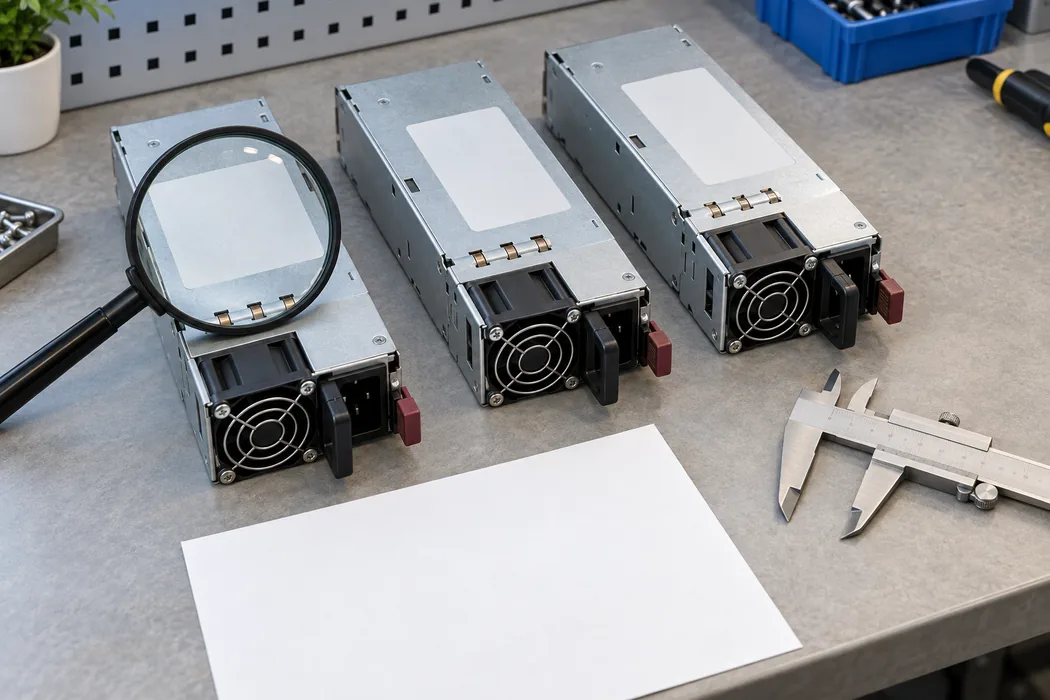
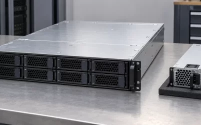
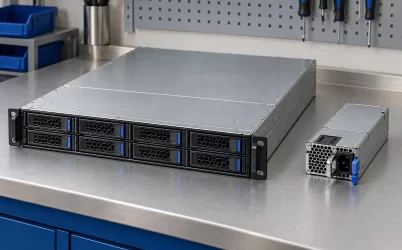
The image illustrates a generic identification workflow, not a verified G1358 nameplate. Compare the actual label and drawing. A familiar handle, fan grille, or 185 mm body establishes neither DC contact assignment nor management compatibility.
Interpret the 12 V and +12.2 V descriptions carefully
Powernexu presents the part as a 12 V supply, while Gospower calls the double-A version a +12.2 V output. That difference may simply reflect nominal-bus terminology versus a specified set point, but the public pages do not give enough information to reconcile it conclusively for the single-A order code. It would be misleading to substitute one figure into a host calculation without knowing the actual regulation band and sensing arrangement. Ask for the output-voltage range across line, load, temperature, and any remote-sense condition. Also confirm the standby output and its rating; neither can be inferred from the main rail alone.
Powernexu’s 12 V and 166.66 A entries multiply to approximately 2000 W. That arithmetic explains the table, but it does not establish the continuous current available at every AC input voltage or inlet temperature. If a controlled sheet specifies +12.2 V at the terminals, the corresponding theoretical current for exactly 2000 W would be about 164 A. That calculation is not a published Gospower output-current limit. Real output capability may be constrained by current limit, airflow, AC line, thermal conditions, and the manufacturer-defined measurement point. Treat the rating table as a starting description, then use the exact revision’s operating curves for design.
A 12 V bus concentrates current at the distribution point. The board-to-module contacts, ORing elements, copper planes, busbars, and branch connectors must each carry the current for their own segment with acceptable temperature rise. At roughly 166 A, even a milliohm of path resistance would dissipate about 28 W under a simple I-squared-R estimate. That is an illustrative calculation for a hypothetical one-milliohm path, not a measured property of this supply. It explains why contact condition and distribution-board design can matter as much as the output label when replacing a high-current module.
Trace the host path from inlet to load
The PSU converts its input to a main DC rail, but a rack server receives power through a mating connector and power distribution board. The PDB may isolate modules, combine rails, provide standby distribution, and feed downstream regulators. Processor and memory rails are created closer to their loads. The module’s advertised wattage is therefore an upstream source rating, not the power available at every device connector after board and conversion losses. An integrator should map which components draw from the main rail, which draw from standby, and where high-current segments are located.
Start with the host’s approved PSU drawing, not a generic CRPS outline. Check the depth datum, guide rails, latch, extraction clearance, AC inlet, connector keying, power contacts, signal contacts, and airflow direction. The Gospower page’s fan-reversal highlight signals that airflow configuration deserves attention, but it does not say which direction a particular shipped unit uses. A module that physically enters the bay can still have an unsuitable airflow direction or signaling configuration. If the installation is a replacement, compare it with the approved incumbent at the full part-number and revision level.
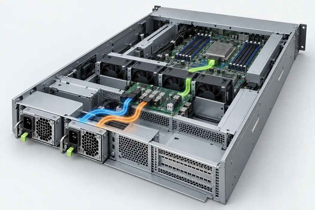
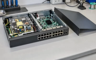
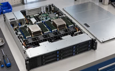
The illustration is a generic open server and power path, not a G1358 schematic. Its useful lesson is the location of interface boundaries: PSU to PDB, PDB to local branches, and branches to loads. Each boundary needs an electrical rating, thermal path, and fault response. An exact-looking exterior is insufficient evidence that the internal paths of two server platforms are the same.
A current budget should follow simultaneous demand rather than the sum of unrelated peak labels. For example, if a hypothetical server draws 1450 W on the 12 V distribution rail during a sustained workload, the source-side current at 12 V is about 121 A before any distribution loss or transient behavior. The example says nothing about this model’s guaranteed headroom. A short GPU or CPU load step may be much higher than the steady value, while the PSU and PDB may respond on different time scales. Obtain the host’s load profile and the module’s documented transient and protection limits before deciding whether a 2000 W supply is adequate.
A 2000 W nameplate does not define every input condition
The Powernexu page lists a 90–264 V AC input window. An input window identifies voltages the unit is listed to accept; it does not state that full output is available throughout that window. Many high-power power supplies have line-dependent power limits, and the actual G1358 curves must be taken from its controlled specification. For a server that can switch between A and B feeds, record the voltage actually seen at each PSU inlet under load and during transfer. The protected operating point is the weaker credible feed condition, not the nominal room supply printed on a facility diagram.
Input current and branch-circuit planning require the specified efficiency and power factor at the relevant operating point. A Titanium designation is not a fixed efficiency percentage. Gospower’s broad T185 introduction states efficiency up to 96.3%; that family statement is not a measured G1358-2000WNA operating point. For circuit sizing, use the exact unit’s maximum input current. For energy estimates, use its efficiency curve at the expected duty profile.
The same distinction applies to cooling. The enclosure dimensions are public, but a 185 mm module may experience very different inlet temperatures in two chassis. Adjacent cables, blocked perforations, fan-control policy, and airflow direction alter local conditions. A cool room does not guarantee a cool PSU inlet. Compare the server’s worst-case inlet-air measurement with the exact model’s permissible operating curve and confirm whether the host can maintain the airflow required at the selected load. Do not assume that a Titanium label supplies the missing thermal limits.
Built-in ORing helps isolate faults but does not create redundancy alone
Gospower lists built-in ORing fault isolation for the double-A product. ORing can prevent one module’s fault or lower output from back-feeding through a shared DC bus, depending on the implementation. It does not establish a supported 1+1 pair, current-sharing behavior, hot-swap sequence, or host-controller compatibility for the single-A part. Those functions span the module, PDB, and server control logic. Ask whether the exact revision is approved to operate with the installed mate and whether mixed suffixes or firmware revisions are supported.
In a 1+1 system intended to survive loss of either module at full workload, the sustained protected load must fit within one surviving module’s allowed output under the relevant feed, temperature, and airflow conditions. Two 2000 W labels do not automatically provide 4000 W of fault-tolerant capacity. If both modules share a 2600 W load in normal operation, losing one would leave a 2000 W-class source facing more than its nominal rating unless the server promptly reduces demand and that behavior is documented. Whether such a temporary condition is survivable requires the actual transient, overload, and power-management specifications.
During removal, contact sequencing and isolation determine what the shared bus experiences. A service technician should not infer hot-swap safety from the phrase “hot pluggable” alone. The host must support the insertion and extraction sequence, prevent access to hazardous energy where applicable, maintain current transfer, and identify the replacement module correctly. The service procedure may also require a warning state, workload limit, or time allowance when only one PSU remains. These details belong to the server platform’s approved maintenance documentation as well as the PSU specification.
Management and status must match the server controller
Gospower’s T185 family description mentions PMBus 1.2 monitoring. That is useful evidence for the family, but it does not publish the complete G1358-2000WNAA command implementation, address configuration, telemetry accuracy, or firmware behavior. It also does not prove that the single-A product exposes identical management functions. A BMC may check manufacturer identity, output status, fault state, fan status, and supported commands before considering a supply healthy. A module that delivers 12 V while reporting unexpected identity or telemetry could still leave the platform in a warning or reduced-power state.
For integration, obtain the host’s accepted PSU list and the exact module’s communication specification. Compare presence and power-good signals, alert behavior, command support, addresses, startup timing, and telemetry units. The practical test is whether the server recognizes both modules, responds correctly to a fault, and records a useful event. Avoid copying a command table from another T185 wattage or suffix. The protocol version alone cannot establish the behavior of every command or the compatibility policy implemented by a particular BMC.
What to put on the replacement record
A useful sourcing record for G1358-2000WNA starts with the exact order code and physical label, then attaches the manufacturer’s controlled electrical and mechanical documents. It should state the approved host and PDB revision, the required airflow direction, the acceptable input source, and whether the unit may be paired with the installed module. If the supplier offers G1358-2000WNAA instead, record a manufacturer-issued equivalence statement or host-vendor approval. An apparent match in power, output class, and enclosure size does not replace that link.
The public evidence supports treating G1358-2000WNA as a 2000 W, 12 V-class Powernexu catalog item and G1358-2000WNAA as Gospower’s documented +12.2 V T185 product. The relationship between those complete identifiers remains the unresolved detail. Once it is documented for the delivered hardware, the host’s electrical, mechanical, thermal, and management requirements determine whether that hardware is suitable. Until then, preserving the final A in every record is the most consequential step in avoiding a false interchangeability claim.