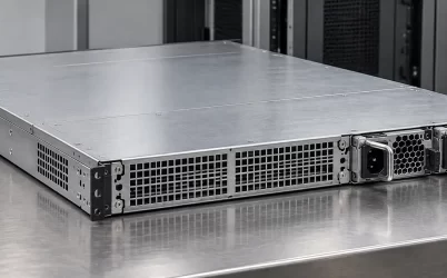
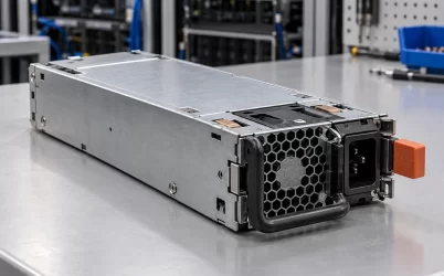
Great Wall’s CRPS2000N3 is a 2000 W Platinum-class CRPS module with a nominal 12 V main output, a +12 V standby output rated at 3 A, and a 185 × 73.5 × 40 mm body. The published main-output line lists 65.6 A, 148 A, and 164 A, but the public table does not say which input, temperature, or operating condition belongs to each figure. That missing mapping is the central issue for a buyer: the highest number cannot safely be assigned to every installation. Use the exact model and its manufacturer document to establish the applicable output envelope before treating it as a replacement or a 2000 W source for a particular server.
Read the CRPS2000N3 record as a set of stated facts
The Great Wall CRPS2000N3 specification page identifies the model, 2000 W rating, 90–264 Vac or 180–320 Vdc input, three main-output current entries, and +12VSB/3 A standby output. It also lists front-to-rear airflow (FR), a 0–55 °C operating-temperature range, Platinum efficiency classification, MEI Class A, and CE, CQC, IRAM, TUV, UKCA, and UL in its safety field. The matching Powernexu CRPS2000N3 product page provides a convenient catalog identity for the same unit. Neither public page supplies a full load-condition table, mating pinout, or server compatibility list.
The published voltage interval describes acceptable input families, not a promise of unchanged output over every point in each interval. Likewise, the 2000 W description is a model rating; its relationship to the listed 12 V currents needs the conditions that the short web table leaves out. A procurement spreadsheet should preserve all three current entries as separate, unassigned published values. Labeling 164 A as the universal continuous limit would add a fact the source does not state.
| Published CRPS2000N3 item | Value | What remains unspecified publicly |
|---|---|---|
| Input | 90–264 Vac or 180–320 Vdc | Current-tier mapping and input-dependent derating |
| Main output | +12 V / 65.6 A, 148 A, 164 A | Condition assigned to each entry |
| Standby | +12VSB / 3 A | Host standby-load allocation and sequence |
| Envelope and airflow | 185 × 73.5 × 40 mm; FR | Mating geometry and host airflow performance |
An OEM drawing, technical manual, and approved host-part list may resolve these omissions. A distributor photograph cannot fill an electrical condition that the original manufacturer has not stated.
The three 12 V entries describe a rating ladder, not three rails
The notation “+12 V / 65.6 A, +12 V / 148 A, +12 V / 164 A” appears under one main-output field. It should not be read as three independently available 12 V rails whose currents can be added. Multiplying each listed current by nominal 12 V gives approximately 787 W, 1776 W, and 1968 W. This calculation translates the table into power scale; it does not establish the exact output power available at any particular AC or DC input. The values are close enough to make the 164 A entry consistent with a roughly 2000 W main-output class, while the lower entries signal potentially important operating limits. The precise correspondence still requires the full manufacturer document.
This matters most when a chassis is being upgraded around a headline wattage. Suppose a hypothetical server needs 1500 W on its 12 V distribution bus during a sustained workload. That load is below the nominal interpretation of 148 A and 164 A, yet it is above the nominal interpretation of 65.6 A. The short public table therefore cannot prove the server is supportable across the whole input range. The buyer needs to know which tier applies at the site’s feed, temperature, and airflow condition. The example is a way to expose the missing datum, not a claim that Great Wall assigns 65.6 A to any particular inlet voltage.
For a lower-load storage or enterprise platform, the distinction may still affect redundant operation. The surviving module may see the full bus demand after its partner is removed, and the relevant current tier is the one available at that surviving module’s actual input. A system that operates normally with two supplies sharing load could fail the one-module case if its assumptions are based on the wrong tier. Conversely, there is no reason to reject the unit simply because the smallest entry appears in the table; that would also assign a condition without evidence.
The current bars visualize the three published entries without attaching unverified voltage or temperature labels. They are a reading aid, not a measured derating curve.
AC and high-voltage DC are two specified input families
CRPS2000N3 accepts 90–264 Vac or 180–320 Vdc according to Great Wall. Those ranges make it a candidate for equipment designed around either an appropriate AC feed or an appropriate high-voltage DC feed. They do not make a rack input automatically compatible. The inlet, upstream protection, grounding arrangement, switching method, and facility power policy must match the chosen feed. For a DC installation, an integrator should establish the bus’s normal and transient limits and confirm that the complete input path remains within the approved interval. For AC, available voltage at the actual module inlet under load is more useful than the nominal voltage printed on a room diagram.
The adjacent 2000 W models illustrate why the suffix matters. Great Wall lists CRPSHD2000D2 with 90–264 Vac or 180–400 Vdc input, giving that HD model a wider published high-voltage DC upper limit. CRPSLD2000D2 instead targets a −40 to −72 Vdc input environment. The LD unit belongs to a fundamentally different source-voltage architecture; the HD unit’s upper DC limit is not evidence that the N3 accepts 400 Vdc. The N3’s 180–320 Vdc range must be preserved when specifying it for a DC bus. All three can be described as 2000 W CRPS products, but that common headline does not erase their input boundaries.
A facility may operate AC servers alongside a DC-fed rack, or have DC bus excursions that fit one module’s interval but exceed another’s. The exact inlet and control arrangement of the host must accept the exact module across the intended envelope. Matching wattage and dimensions miss the input-voltage difference before reaching the connector question.

The two bounded input windows show the N3’s published AC and DC families. No path in the diagram implies permission to connect the same module to both sources simultaneously.
Where the N3 family helps identification—and where it stops
Great Wall’s public CRPS listing also includes CRPS1600N3. It shares the stated 185 × 73.5 × 40 mm envelope, 90–264 Vac or 180–320 Vdc input families, FR airflow, Platinum classification, and +12VSB/3 A standby entry with CRPS2000N3. Its nominal output is 1600 W, and its main-output entries are 65.6 A and 131.1 A rather than the 2000 N3 model’s three current figures. The matching N3 suffix and dimensions therefore identify a nearby family, not identical electrical capacity or established interchangeability.
This family relationship is useful in inventory review. A warehouse label reading only “N3 CRPS” is insufficient to distinguish the two capacities. Recording the complete model, revision, and original part number prevents a 1600 W variant from being treated as the 2000 W article because the bodies look alike. In service spares, the chassis maker’s approved list is stronger evidence than family resemblance. The two units may share a bay design, but the public data does not establish identical connector assignment, firmware behavior, current sharing, or host approval.
Mechanical dimensions are likewise only three measurements of the module body. A host bay still has guide rails, latch engagement, extraction clearance, a rear connector datum, and an inlet/cable arrangement. An apparently complete insertion can be electrically wrong if the mating system or control contacts differ. A 185 mm length also says nothing about how much clearance remains behind the installed server for a hand, cable bend, or service pull. The FR airflow entry identifies the model’s specified direction; a chassis with the opposite designed flow should not rely on shape alone to justify installation.
The official listing does not publish a CRPS2000N3 pin map or a complete management protocol description. Avoid copying a pinout or PMBus register set from another CRPS model. That caution is particularly relevant when a new PDB is being designed: board layout decisions around power contacts, standby contacts, control signals, and communication must follow the actual approved interface drawing, not a generic drawing found for an adjacent product.
A 2000 W module is a component of a bounded server power path
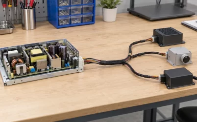
The main 12 V output is a supply to the host distribution system, not a promise that 164 A can be delivered through any single board trace or cable. Contact resistance, copper geometry, connector temperature, and the downstream converters determine the usable path to processors, accelerators, storage, and fans. The +12VSB/3 A entry serves the host’s standby state; it does not automatically define the power available to every management board. The BMC, backplane, and startup sequence must be matched to the module’s actual interface.
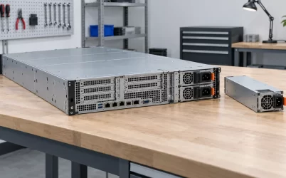
A plausible high-density server may use two CRPS modules, but the enclosure’s PDB determines how their outputs combine and how faults are isolated. A two-module assembly does not automatically create a 4000 W failure-tolerant server. In a 1+1 arrangement, either single surviving module must be capable of supporting the required load under its applicable input and environmental conditions. If each module only covers half the normal load, the pair may increase total capacity without providing one-module continuity. For this model, the missing current-tier mapping makes the surviving-capacity question especially important.
Hot insertion and removal similarly rely on the host interface. The system has to manage contact sequencing, inrush, load transfer, isolation of a failed module, and controller response. Great Wall’s short N3 table does not provide the timing or signal detail needed to claim a specific server can exchange it while energized. A service technician should use the chassis vendor’s procedure and approved spare identity. The model’s published dimensions and airflow do not replace that approval.
At 0–55 °C, the stated operating range applies to the module under conditions defined by its technical documentation. A rack’s room temperature is not necessarily the air temperature entering a power module. Heated exhaust recirculation and restricted rear clearance can raise the local inlet temperature, while the module’s own losses add heat to the flow path. The short listing provides neither a pressure-flow requirement nor a detailed temperature derating curve. An integrator assessing a dense bay should obtain those documents instead of treating 55 °C as a universal full-output guarantee.
Resolve the missing condition before approving an N3 replacement
The strongest use of the public data is to separate established facts from open conditions. CRPS2000N3 is a specific Great Wall 2000 W, Platinum, 12 V CRPS model with stated AC and high-voltage DC input intervals, three published main-current entries, a 3 A standby entry, FR airflow, and a defined body envelope. Those facts support initial sourcing and eliminate some unsuitable substitutions. They do not identify which of the three currents applies to a rack’s input, prove a particular 1+1 surviving load, or identify an approved server bay.
Ask the manufacturer or authorized channel for the exact revision’s technical manual and an output table that maps 65.6 A, 148 A, and 164 A to explicit conditions. Pair that document with the host’s approved module list or mating-interface specification. If the project uses DC input, verify the bus against the N3’s 180–320 Vdc range, rather than importing the HD model’s 400 Vdc upper limit or the LD model’s negative-voltage plant assumptions. If a system is being designed around redundancy, compare the actual one-module load with the current tier valid after the partner fails. The publication-ready answer to “can CRPS2000N3 replace this PSU?” is conditional until those records agree on the exact module, source, interface, and operating state.