An accelerator core, an SSD controller, and management electronics can each need point-of-load regulation inside an AI server. Their converters serve different electrical requirements. A device described as suitable for AI servers therefore needs a more specific assignment before its current rating, efficiency, or package size becomes useful: which rail will it supply, and what behavior does that load require?
Point-of-load (POL) DC-DC converters create regulated local supplies near their receiving circuitry. For rail-specific selection, begin with the load manufacturer’s power requirements, then choose an implementation capable of providing the required voltage, current, control, and operating sequence. A compact regulator appropriate for a supporting circuit does not establish accelerator-core suitability. Conversely, a sophisticated core-regulation architecture can impose unnecessary components and control complexity on a modest fixed-voltage rail. The useful comparison separates those jobs before comparing candidate devices.
Accelerator-core regulation starts with the processor’s power specification
A processor core rail can require more than maintaining one nominal output voltage. Depending on the processor, its specification may define commanded voltage changes, intentional load-line behavior, current reporting, fault indications, and transitions between operating states. These requirements determine which regulator controllers are eligible before power-stage capacity is considered.
A load line deliberately changes the regulated voltage target with current under a defined rule. It should not be confused with uncontrolled voltage loss. A converter offering excellent fixed-output accuracy may still lack the control behavior required by a particular processor. Likewise, adjustable output voltage does not establish support for the processor’s command protocol or its timing requirements.
Where a core rail uses a multiphase implementation, a controller coordinates several switching phases feeding the same output. Distributing current among phases can help manage component loading and heat. Interleaving also changes ripple behavior. The usable result depends on the implemented controller, stages, inductors, and operating conditions; multiplying a stage’s headline current by phase count does not establish continuous rail capacity.
Current limits introduce another distinction. A power stage’s electrical rating, the controller’s configured protection threshold, and the processor’s permitted demand are separate quantities. A higher protection threshold does not authorize additional continuous loading. Phase-current imbalance can also make one stage reach a limiting condition before the average phase current appears excessive.
For a core-rail candidate, the decisive evidence is a documented relationship between the processor’s requirements and the proposed regulation implementation. That relationship may come through a processor design specification and an applicable manufacturer reference design. An application page mentioning GPUs supplies useful discovery context, but cannot establish that relationship for every accelerator generation.
Supporting rails need their own load descriptions
Auxiliary rails can supply storage controllers, management processors, interface circuitry, or other supporting electronics. Their requirements vary substantially. Some use a fixed voltage with a simple enable input; others need controlled sequencing, low-noise behavior, or coordinated shutdown. Calling a rail auxiliary describes its role, not its tolerance or operational importance.
For storage, distinguish the power accepted by a complete drive from the lower rails generated inside it. A converter used within an SSD is not automatically a replacement for the supply feeding the drive connector. The receiving component and the conversion boundary must match the proposed application. This distinction prevents a server-storage example from becoming an unsupported recommendation for either a complete drive or an accelerator core.
A shared auxiliary rail deserves attention to its connected population. Several loads may fit within continuous current capacity while requiring different startup order or shutdown behavior. Separating those loads into independently controlled rails can simplify sequencing and fault reporting, although it adds conversion circuitry. Sharing is attractive when their voltage requirements and permitted operating states genuinely agree.
Light-load behavior can matter more here than on a heavily loaded core rail. Some converters change switching mode to reduce consumption at low demand. Depending on the implementation, that change can alter ripple or switching-frequency content. A candidate’s efficiency advantage is useful only if the resulting output behavior remains acceptable to the supporting circuitry.
Upstream bus choice is a separate architectural question. Powernexu’s server power supply voltage map explains where distribution voltages and local rails belong. Once that boundary is established, the supporting-rail task is narrower: select the regulator for the actual receiving load, including the states in which that load remains powered.
Integration changes which components the designer still owns
A monolithic buck regulator integrates switching transistors with control circuitry. A controller-based implementation uses external switching devices or power stages. A power module may integrate additional components, potentially including magnetics, but the included functions must come from its documentation. The terms integrated regulator and power module should not be treated as interchangeable bills of materials.
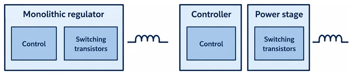
Analog Devices’ technical discussion of POL implementations describes the placement trade-off between controllers with external switching devices and monolithic regulators. It also identifies heat as a constraint on compact integration. The practical implication is to compare complete implementations, including external components and heat removal.
An integrated switching stage can reduce component count while still requiring an external inductor, capacitors, configuration components, and suitable board copper. The IC package outline therefore describes only part of the occupied area. Keep component keepouts, routing access, and any required cooling provisions in the comparison. A smaller chip can belong to a larger installed solution.
A controller with external stages offers different design freedom. The designer can select switching stages and magnetics for the required duty within the controller’s supported implementation. That flexibility brings responsibility for component compatibility, current sensing, switching layout, and thermal distribution. It is valuable when those choices solve a real rail requirement, rather than simply increasing the number of adjustable parameters.
Integration can also change the scope of substitution. Replacing a controller, power stage, or module may affect compensation, sensing calibration, switching timing, or protection behavior. Similar package dimensions and nominal current do not establish equivalent operation. For technical purchasing, the relevant item is the documented converter implementation and its permitted component alternatives.
Control requirements extend into startup and the off state
A rail’s required behavior includes the periods before normal regulation and after disable. Core supplies may participate in processor-controlled state transitions. Supporting supplies may need to start earlier, remain available during standby, or discharge before another rail restarts. These relationships can eliminate an otherwise attractive converter without any shortage of continuous current.
Prebias is one example. A converter output can already carry voltage when startup begins because another circuit or retained charge energizes it. The converter’s documented startup behavior must suit that condition. A soft-start feature alone does not establish acceptable prebiased startup, because the switching and discharge behavior remain device-specific.
Power-good signaling also needs a defined meaning. Its assertion window, delay, output type, and behavior during disable determine whether downstream logic can use it. A status signal suitable for one sequencer may need additional circuitry for another. Presence of a power-good pin does not establish the required startup sequence.
Telemetry and fast regulation perform different tasks. Where a converter provides a digital management interface, supported commands, measurement accuracy, update behavior, and fault reporting need to match the host implementation. A management interface should not be assumed to provide a processor’s voltage-command interface. Slow current reporting also cannot characterize a fast load transition.
Fault recovery can change the server’s operating sequence. Automatic retry may be appropriate for one supporting rail, while another load requires a controlled reset before power returns. Latching shutdown can preserve a fault state but needs an available recovery mechanism. Select the behavior that serves the receiving circuitry and system policy; protection acronyms alone leave that behavior unspecified.
Compare current, efficiency, and transient figures on matching terms
Two candidates become meaningfully comparable when their figures describe the same rail duty. For current capability, retain output voltage, input voltage, switching frequency, cooling, board construction, and relevant temperature limits. A stated maximum current can describe an electrical ceiling, a demonstrated operating point, or a thermally qualified condition. Those evidence types support different conclusions.
Peak efficiency requires similar care. One candidate may reach its peak at a load the rail rarely uses. Another may perform better over the rail’s common operating states. Compare applicable curves across the expected demand distribution, including standby where relevant. Keep external-component and auxiliary-control losses within a consistent measurement boundary.
Transient demonstrations require more than matching the current-step magnitude. Starting current, ending current, transition rate, repetition, input condition, output capacitance, and measurement location affect the waveform. A smaller excursion obtained with substantially more capacitance does not isolate a converter advantage. It describes a different implementation whose space and startup consequences also belong in the comparison.
The load’s voltage requirement determines what counts as acceptable response. A fixed auxiliary rail may have a different permitted envelope from a processor rail following a specified load line. Comparing their voltage excursions without those definitions can rank an implementation favorably for behavior that its intended load does not request.
Typical plots are useful engineering evidence, but they should remain identified as typical. Guaranteed limits and their conditions serve a different purpose. Where a candidate lacks data for a consequential condition, request that evidence rather than extrapolating a favorable curve. Missing hot-condition data leaves hot-condition capability unresolved; it does not prove that the converter will fail.
The same distinction applies to demonstration boards. Their results belong to the documented components, layout, and operating setup. A production board with different inductors, capacitance, or cooling can behave differently. Use evaluation evidence to understand the candidate and its dependencies, then carry those dependencies into the intended implementation.
One server can justify several different POL implementations
The processor’s main cooling assembly does not establish the cooling available to nearby regulators. A cold plate can remove processor heat while power stages rely on board conduction and local air movement. Conversely, a supported thermal interface may provide a deliberate path for regulator heat. These are different installations, even when they occupy similar board area.
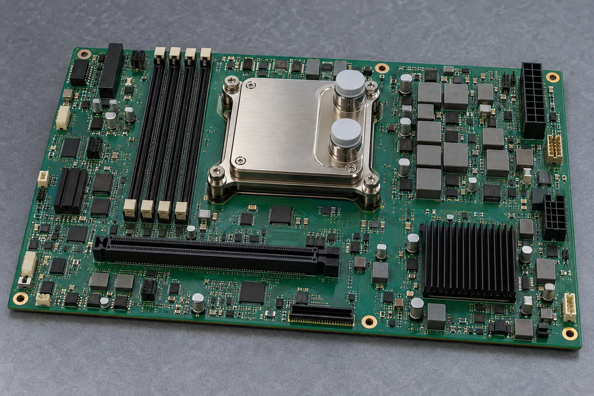
Concentrating circuitry into a compact device can simplify assembly while creating a localized thermal burden. Distributing switching stages can spread dissipation but consume more placement area and routing resources. Compare junction and component temperatures under the candidate’s actual thermal arrangement. A board-average temperature or processor temperature cannot substitute for those local conditions.
This leads naturally to a mixed converter population. A processor core may justify a controller and coordinated power stages because its current and control requirements demand that implementation. A fixed supporting rail may favor a monolithic regulator when its documented operating envelope fits. A module with integrated magnetics may be attractive where reduced external-component work and available cooling outweigh its other constraints.
Standardizing every rail on one device family can simplify sourcing, but may add unnecessary circuitry or leave required functions absent. A more useful commonality target can be a shared design practice, documentation format, or approved component set while preserving different regulator implementations. Electrical suitability should survive the purchasing simplification.
No exact processor power specification or candidate converter datasheet accompanies this article, so it assigns no model to a core or auxiliary rail. The resulting distinction is nevertheless actionable: core candidates need the processor’s required regulation and command behavior; supporting-rail candidates need their particular voltage, sequence, and load behavior. After those assignments, integration, comparable performance evidence, and installed cooling determine which implementation earns its place.