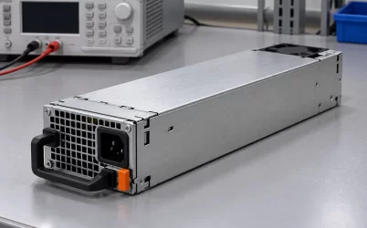
CRPSLD2000D2 is Great Wall’s 2,000 W CRPS module for a −40 to −72 Vdc input plant and a nominal +12 V output. Its defining question is whether a particular −48 V distribution system can feed the module through its entire operating range, especially at the low-voltage end where input current rises. Great Wall lists +12 V/161 A, +12VSB/3 A, a 185 × 73.5 × 40 mm body, FR airflow and a 0–50°C operating interval. Those facts establish a candidate for a DC-fed server or telecom shelf; they do not establish its connector, upstream breaker, live-insertion behavior or approval for a particular host.
What the exact LD model establishes
The Great Wall CRPSLD2000D2 listing specifies −40 to −72 Vdc input, 2,000 W output, +12 V/161 A main output and +12VSB/3 A standby. It also lists Platinum efficiency, CCC and CE, MEI Class A, FR airflow and a 0–50°C operating range. The Powernexu product record repeats those headline values. The manufacturer’s public table does not provide an input-current curve, an efficiency curve, a pin assignment or a power-versus-temperature derating table. These omissions matter more to an installed −48 V system than another generic description of CRPS packaging.
The 161 A main rail corresponds to 1,932 W at exactly 12 V, close to the 2,000 W headline. That does not establish a second rail or hidden current allowance. The short public table does not explain the difference. Obtain the revision-controlled datasheet before allocating it in a load budget. The separately stated 12 V standby output has a 36 W voltage-times-current product; the public row does not say whether it is included in a combined output limit.
LD identifies the low-voltage DC input member in this comparison. CRPSHD2000D2, a nearby 2,000 W Great Wall model, instead lists 90–264 Vac or 180–400 Vdc. It serves a different feed architecture. The modules have the same published external dimensions, but matching wattage and dimensions do not authorize substitution. In particular, an HD unit cannot be assumed to start from a −48 V plant, and an LD unit cannot be assumed to accept a 380 Vdc rack bus or ordinary AC mains.
The −48 V bus is a range, not a single voltage
A nominal −48 V telecom supply changes voltage with rectifier regulation, battery charging, discharge, cable drop and protection-device impedance. The published −40 to −72 Vdc window should be compared with voltage at the CRPS input contacts in every intended power state. A site diagram labeled “−48 V” is insufficient if the module sees a lower voltage during discharge or a higher one during charging. Polarity convention, return bonding and isolation also have to come from the controlled system drawing; the model’s input-range line does not define the connector pins or grounding scheme.
At a fixed output load, lower input-voltage magnitude means higher input current. For 2,000 W output, an impossible lossless converter would need 50 A at a 40 V input magnitude and about 27.8 A at 72 V. Real current exceeds both figures because conversion loses energy. These are lower bounds for reasoning about the feed, not manufacturer input-current ratings. They show why a branch sized around nominal 48 V can be stressed most heavily near the bottom of the supported input range. Continuous rating, connector heating, conductor drop and protective-device coordination need a validated maximum-current value.
For illustration, assume a 1,600 W load and 90% conversion efficiency at one operating point. Input demand would be about 1,778 W. At 40 V magnitude the approximate current would be 44.4 A; at 48 V it would be 37.0 A. The 90% figure is a hypothetical assumption, not a published CRPSLD2000D2 test result. A real design should replace it with the manufacturer curve at the relevant input, load and temperature. The example’s useful result is the direction and scale of the change: low plant voltage raises the current burden even when the 12 V load remains steady.
Trace the input path before assigning the module a breaker
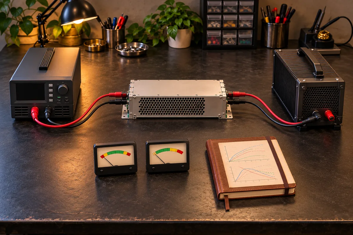
The input path commonly runs from the DC plant through distribution protection and wiring to a shelf connector or power distribution board, then to the module. Each segment has a current and temperature rating. A breaker chosen solely from a 2,000 W label can be too small during low-voltage operation or too large to protect a particular cable. The correct choice depends on the verified input-current envelope, conductor installation, branch fault current, interrupting capacity and applicable site rules. The public module listing is not a protective-device schedule.
Voltage drop is part of the same problem. Suppose the total source-to-module loop resistance is 20 milliohms and current is 45 A. The drop would be about 0.9 V and the path would dissipate about 40.5 W, using I²R. Those assumed values describe no specific Great Wall installation. In a plant approaching the −40 V limit, the drop consumes some of the remaining voltage margin. Connector wear or a loose termination can increase local resistance and create concentrated heat without a large change at the plant’s monitoring point.
Record voltage where the module actually receives power, particularly during the lowest battery voltage and the largest expected equipment load. A controller that reports 40.5 V at a distant distribution bus does not prove 40.5 V at the CRPS interface. Similarly, a bench supply with short leads may hide an installation loss that appears in a long rack harness. The useful design number is the voltage envelope at the receiving contacts, including credible transients, rather than an unqualified nominal bus value.
A high-capacity battery plant can also deliver substantial fault energy. The shelf’s input protection, precharge or inrush management, contact spacing and isolation procedure require their own evidence. A CRPS form factor often suggests serviceable modules, but the public CRPSLD2000D2 row does not specify whether insertion under load is permitted on a particular DC shelf. That question belongs to the complete module-and-host interface. Do not translate a chassis handle or blind-mate outline into permission for live service.
Move from the 12 V rating to a server load
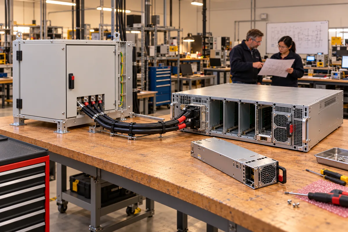
The 12 V bus feeds a distribution board and often point-of-load converters before it reaches processors, memory and network hardware. A server’s component power figures cannot simply be added and compared with 2,000 W if they describe different electrical points. Separate power measured at the module output from power consumed after DC/DC conversion. For example, a board converter delivering 300 W at an assumed 90% efficiency would draw about 333 W from the 12 V bus at that operating point. Its transient input draw and startup sequence may impose another limit.
At nominal 12 V, a sustained 1,500 W module-output demand is about 125 A. That is below the published 161 A main-current figure, leaving 36 A of simple arithmetic difference. The calculation does not establish allowable transient duration or full-output availability at 50°C. Nor does it settle how the standby output is included. A proposed system should have a measured or bounded 12 V load profile, and the applicable manufacturer rating conditions should be tied to the actual installation. The arithmetic is a screening step, not a product performance claim.
High current also makes the mating path important. As an illustration, one milliohm carrying 161 A would dissipate about 25.9 W. That is an intentionally simple I²R example, not a measured connector resistance. It explains why contact design and current distribution cannot be inferred from matching module dimensions. The host’s power board must carry current through its connector, copper, protection elements and downstream branches without exceeding their own limits. A spare module with the right output voltage could still fail that physical interface test.
The 3 A standby rail supports whatever control circuits the approved host assigns to it. The public listing does not document its pinout, power-good behavior, telemetry, sequencing or share-control signals. Request the host interface drawing when replacing a module or building a new shelf. If a server management controller expects a particular presence or status response, voltage matching alone will not make the module operational. Those details are especially consequential in a remotely managed edge location where a failed start may require a site visit.
What the 185 mm envelope and FR airflow do and do not prove
Great Wall gives dimensions of 185 × 73.5 × 40 mm. This is a useful first screen for depth, width and height, but a module bay also has rails, latch positions, stop surfaces, connector engagement depth, extraction space and airflow openings. Compare a mechanical drawing of the actual CRPSLD2000D2 revision with the shelf drawing. A module that slides into a bay may still fail to mate fully or latch securely. A complete fit review includes the space needed to remove it without disturbing neighboring cables.
FR is the manufacturer’s listed airflow direction. Confirm its orientation using the module drawing and the installed shelf, then follow where warm air goes after leaving the PSU. A cabinet fan can oppose a module fan or recirculate its exhaust. The stated 0–50°C operating interval does not itself promise 2,000 W at every inlet temperature in that interval. Because the public row has no derating curve, the highest-load, highest-inlet-temperature combination calls for the revision-specific rating data. Measure inlet air at the module in a fully populated rack; room temperature can be appreciably lower.
The Platinum label is a published efficiency classification, but the Great Wall listing does not provide a CRPSLD2000D2 loss map across −40 to −72 V input and varying load. A precise heat or electricity-cost prediction therefore needs more data. For system thermal planning, electrical losses and the direction of forced air matter together. If the module runs at high load during battery operation, the upstream plant and cabinet cooling must both handle that state, even though the source voltage may be lower than during rectifier operation.
LD and HD solve different continuity problems
A −48 V plant is often backed by batteries and rectifiers. CRPSLD2000D2 can be considered where that plant presents a voltage within its published window at the receiving interface. Its architecture keeps the server’s power conversion attached to the low-voltage DC distribution. The HD model’s published DC window starts at 180 V and extends to 400 V, while also allowing AC input. That architecture may suit a high-voltage DC rack or an AC installation, but it is not a replacement for a low-voltage battery feed. Similar product codes should be checked character by character on an order, a spare label and the receiving host’s approved-parts list.
Continuity also depends on what remains after a failure. In a two-module shelf configured for 1+1 redundancy, the protected load must fit within one module’s applicable output rating, including its input and thermal conditions. Two 2,000 W labels do not make a 4,000 W protected load. If both modules draw from one distribution breaker or battery string, a failure there can remove both modules. Conversely, truly independent feeds require appropriate shelf wiring and isolation; the PSU product row does not establish that topology. Treat the DC plant, distribution branches and PSU modules as separate failure domains.
For a site with a nominal −48 V battery bus and a 1,400 W server output demand, the LD input range and 161 A main-output listing make this exact model worth examining. The decisive remaining questions are whether the bus stays inside −40 to −72 V at the module during discharge and charging, whether the input branch is rated for the validated low-voltage current, whether the host interface approves this revision, and whether a single surviving module supports the load at its actual inlet temperature. If those answers are unavailable, the public specification supports a shortlist, not an interchangeability or uptime claim.