“2U power supply noise” can describe two different problems. A person beside a rack usually means audible sound: a fan, vibration, or a changing tone. A power-supply specification may instead mean electrical ripple and noise on a DC output, measured in millivolts with an oscilloscope. One cannot be inferred from the other. If the complaint is audible, identify whether it comes from the PSU module, the server’s other fans, or nearby hardware before changing anything. If the concern comes from a data sheet or an unstable load, identify the output rail, measurement bandwidth, load, and probe location. The fact that equipment occupies two rack units does not establish either a quiet fan or a low-noise electrical output.
The same word leads to different instruments
Acoustic noise is a pressure variation in air that a person can hear. Product literature might express it as sound pressure in dB(A), but a number without its distance, measurement position, background level, load, and inlet temperature is difficult to compare. A server may produce an objectionable narrow tone even when its overall sound level seems moderate. A change in fan speed can move that tone without greatly changing an averaged reading. A microphone measures the assembled machine and the room around it; it does not automatically isolate the PSU.
Electrical output noise describes variation superimposed on a nominally regulated DC rail. It is commonly given as peak-to-peak voltage at a stated measurement bandwidth, sometimes together with a ripple limit. A scope trace, a differential measurement arrangement, and the specified load condition belong to this question. It cannot be heard simply because it is called “noise.” A noisy fan is not evidence that the DC rail exceeds its ripple specification; a quiet rack is not proof that the rail is clean.
Manufacturers use the wording in both senses. Advanced Energy describes its LCM600 as a 2U-high front-end supply and gives a “Noise” value in its electrical specifications. That entry concerns output voltage variation, not the sound heard across a room. Conversely, server service material may discuss an acoustic mode or a fan speed without saying anything about output ripple. The right first question is therefore not “How much noise does a 2U PSU make?” It is “Which physical quantity is being reported, and at which boundary was it observed?”
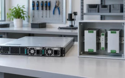
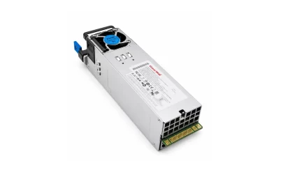
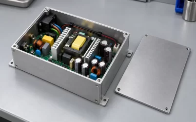
Two units may carry the same 2U label while serving different systems. One may be an enclosed supply mounted inside a rack unit; another may be a removable server module in a common power bay; a rack power shelf may occupy 2U while containing several converters. Their sound sources, downstream rails, and measurement access differ. Treat the rack height as a packaging clue, not a test method or a performance grade.
The audible source may be elsewhere in the 2U chassis
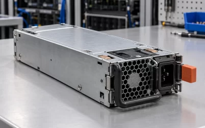
The rear of a 2U server often presents several spinning devices within a small area. A PSU may have an integral fan, but the chassis can also have a fan wall, drive cooling, and fans attached to accelerator or networking hardware. Sound reflected from a rack rear door or a cable bundle can make the loudest component appear to be at a different position. Listening from the front and rear at a safe distance, while noting the machine’s operating state, is more informative than assuming the PSU is responsible because its exhaust grille is visible.
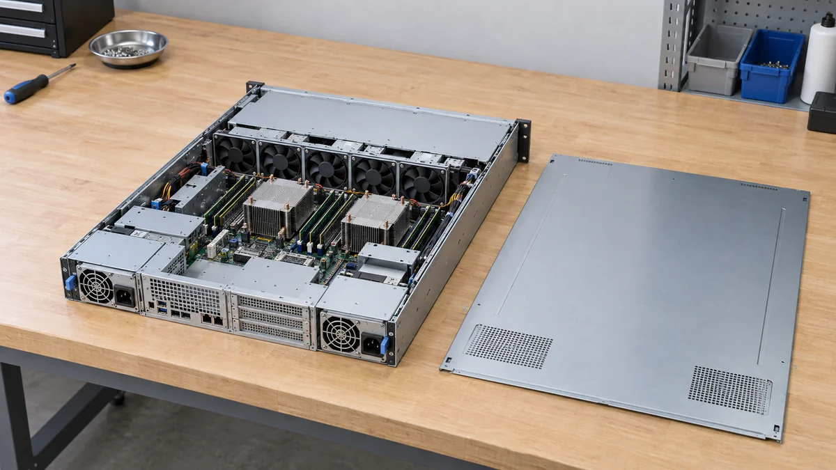
A concrete example shows why attribution matters. The Intel Server System R2600SR technical specification describes a 2U, multi-node machine with five dual-rotor hot-swap system fans, while each power-supply module has its own fan. Its management system distinguishes system-fan status from power-supply fan status and offers several acoustic modes. Those are properties of that specific platform, not a rule that every 2U server has five fans or configurable modes. They demonstrate that a sound near a PSU bay can have several possible sources, and the platform may already expose evidence to separate them.
Height by itself cannot predict which fan dominates. A 2U enclosure can permit a different fan diameter or air path from a 1U enclosure, but it may also contain more processors, denser drives, hotter accelerators, or more severe rear-door restriction. A fan’s operating speed follows the pressure and heat it must handle, the host control policy, and the installed hardware. More vertical space can help a particular design; it is not an acoustic guarantee. Comparing a bare PSU specification with a fully populated 2U server is particularly misleading because the latter includes all of the other fans and air-path losses.
Airflow resistance can change the sound without changing the PSU model. A missing blanking panel, damaged baffle, blocked inlet, clogged filter where one is specified, or tightly packed cables may redirect air and provoke a higher fan command. A rack door can impose pressure loss or reflect tonal sound. These relationships do not authorize bypassing the enclosure’s designed airflow features; they explain why an apparently identical PSU can sound different after installation. The useful observation is whether the sound tracks a controlled change in server load, inlet condition, fan status, or rack configuration—not whether the chassis is nominally 2U.
Time and operating state narrow an acoustic complaint
A short sound at startup, a steady rushing sound, a periodic speed surge, a rhythmic click, and a new grinding tone are different observations. Startup can briefly command fans to a high speed on some platforms; that behavior is not proof of a faulty PSU. A sustained rise after workload increases may reflect a valid thermal response. Repeated cycling at idle may point toward a control or sensor issue, a changing inlet temperature, or a fan that cannot maintain its commanded speed. These are possibilities, not diagnoses from sound alone.
Record when the change began and what happened at the same time: a firmware update, module replacement, drive addition, fan fault message, rack-door change, or shift in the workload. If the management interface exposes actual fan speed, commanded speed, PSU health, and temperature, compare those time-aligned readings rather than relying on the loudness impression. Some platforms expose only a subset of these values. A healthy-status flag is useful but not absolute evidence about bearing condition or airborne sound; management telemetry answers the questions its sensors were designed to measure.
Redundant power adds another variable. With two active modules, their load contributions and fan commands may differ. After one module is removed or loses input, the survivor may carry more current and dissipate more heat; its fan may respond, while chassis fans can also change if the system enters a degraded policy. A new noise after that event does not by itself prove the survivor is defective. Check the platform’s event record and whether the remaining module can support the permitted load under the current input and cooling conditions. Do not deliberately remove a supply from a live server simply to locate a sound unless the host’s approved service procedure and surviving capacity are established.
A clicking, scraping, or intermittent tone should not be “fixed” by opening an energized PSU or substituting an arbitrary fan. Stored energy and cooling qualifications make that unsafe. Nonintrusive listening, management readings, and model-specific service documentation define the appropriate boundary for initial assessment. If a fault indicator or repeated power interruption accompanies the sound, preserve the event timeline and follow the supported service route. A 2U package offers more height than 1U, but it does not remove the electrical hazard inside a converter or make a nonapproved module interchangeable.
Output ripple is a rail specification, not a room complaint
For electrical noise, begin at the DC output identified by the actual power-supply document. Peak-to-peak ripple is the difference between the highest and lowest voltage in the specified measurement window, and the result depends strongly on the measurement setup. Probe-ground length can collect switching fields, while a different bandwidth can include or exclude high-frequency components. Loading, input voltage, operating temperature, and installed filtering can also change the trace. Two printed millivolt limits are not comparable if their measurement methods and output rails differ.
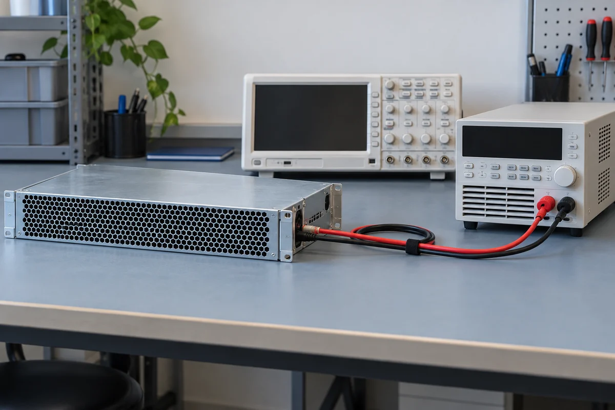
The DC boundary matters as much as the instrument. A server module may feed a PDB or backplane, then cables or copper planes, and finally point-of-load converters near processors or memory. A ripple limit at the module’s output contacts does not describe every downstream rail. Conversely, an oscillation observed at a motherboard rail is not automatically generated inside the removable PSU. The intervening distribution path, load transients, sensing, and local conversion stages can influence the waveform. The specification and the symptom must refer to the same electrical node before a claim of noncompliance is meaningful.
For a system that experiences resets or interface errors, the question is not whether an operator can hear the PSU. A controlled electrical investigation would compare the documented output limit, the exact rail and load state, the relevant measurement method, and the platform’s own event information. Such work belongs to qualified personnel using appropriate instruments and a safe test arrangement. The article’s distinction is conceptual rather than an invitation to probe a live high-current bus inside an unfamiliar server. An apparent ripple problem can also be caused by the measurement technique itself, which is why an unqualified scope screenshot should not be treated as a final diagnosis.
Match the evidence to the meaning of noise
If the search began with a loud rack, the meaningful comparison is an acoustic one under comparable conditions: the assembled 2U server, the same workload class, inlet temperature, fan-control policy, rack configuration, microphone position, and background sound. An isolated PSU dB(A) statement may help narrow candidates, but it cannot predict the total sound of a populated server. If the search began with a supplier specification, confirm whether “noise” is in mV peak-to-peak, in dB(A), or in another clearly identified unit before treating it as relevant to the concern.
A particularly useful separation is PSU fan speed versus system-fan speed. Where the platform reports both, a loudness rise that coincides with only the system-fan command points to a different line of inquiry from one that follows the PSU fan. This is not a calibrated sound-source measurement; airflow and reflected sound can still mislead. It is a way to avoid replacing a healthy converter because a nearby chassis fan responds to processor heat. The Intel example illustrates how a specific server can expose both domains, but other 2U hosts may offer less detail.
This also avoids an easy but unhelpful substitution. Choosing a lower-wattage or higher-efficiency PSU solely to reduce noise may change heat generation, yet it might force the remaining converter nearer a high-load region or violate the server’s compatibility and redundancy policy. Selecting a slower fan without the host’s thermal approval can raise component temperatures. A quieter result must preserve the machine’s supported cooling and power state. The acoustic issue is solved at the source that produces the sound; an electrical ripple issue is solved at the rail and measurement boundary where it exists.
What a 2U label can—and cannot—tell you
For an audible complaint, start with the complete machine and its operating timeline, then use the host’s fan and fault information to assign a probable source without opening the converter. For an electrical specification question, read the output rail, units, bandwidth, load and probe conditions before comparing two numbers. The two paths need not be blended into one troubleshooting checklist. They answer different questions, use different instruments, and can lead to different corrective actions even when both appear under the same search phrase, “2U power supply noise.”