Remote console access, hardware inventory, and a network power-on request can require several circuits to remain powered while a server’s main output is disabled. For an 850 watt CRPS server PSU, those functions need a separate auxiliary-load budget. The 850W headline does not establish how much power reaches the management domain, which consumers share that allowance, or whether the published standby rating applies in the required operating state.
The useful starting point is a schedule of simultaneous management loads at a defined electrical boundary. Translate that schedule into demand at the PSU’s standby output, then compare it with the exact candidate’s documented limits. Two manufacturer specifications below provide standby voltage and current entries, but leave important operating-state and allocation questions unanswered. They support a preliminary capacity comparison; neither establishes a complete remote-management solution for an identified host.
Count the functions that must coexist before main power starts
Begin with the service the management domain must provide. A host required only to receive a wake request can have a different load schedule from one required to maintain a remote console, collect inventory, and communicate with attached management devices. Assign demand to the hardware performing those functions rather than treating each software feature as an independent electrical load.
A management processor and its memory might already be included in one board-level power figure. Adding separate processor and memory estimates would then count the same consumption twice. Conversely, a figure covering that board might exclude its network interface or a distribution-board controller. Preserve the coverage of each input before adding the numbers.
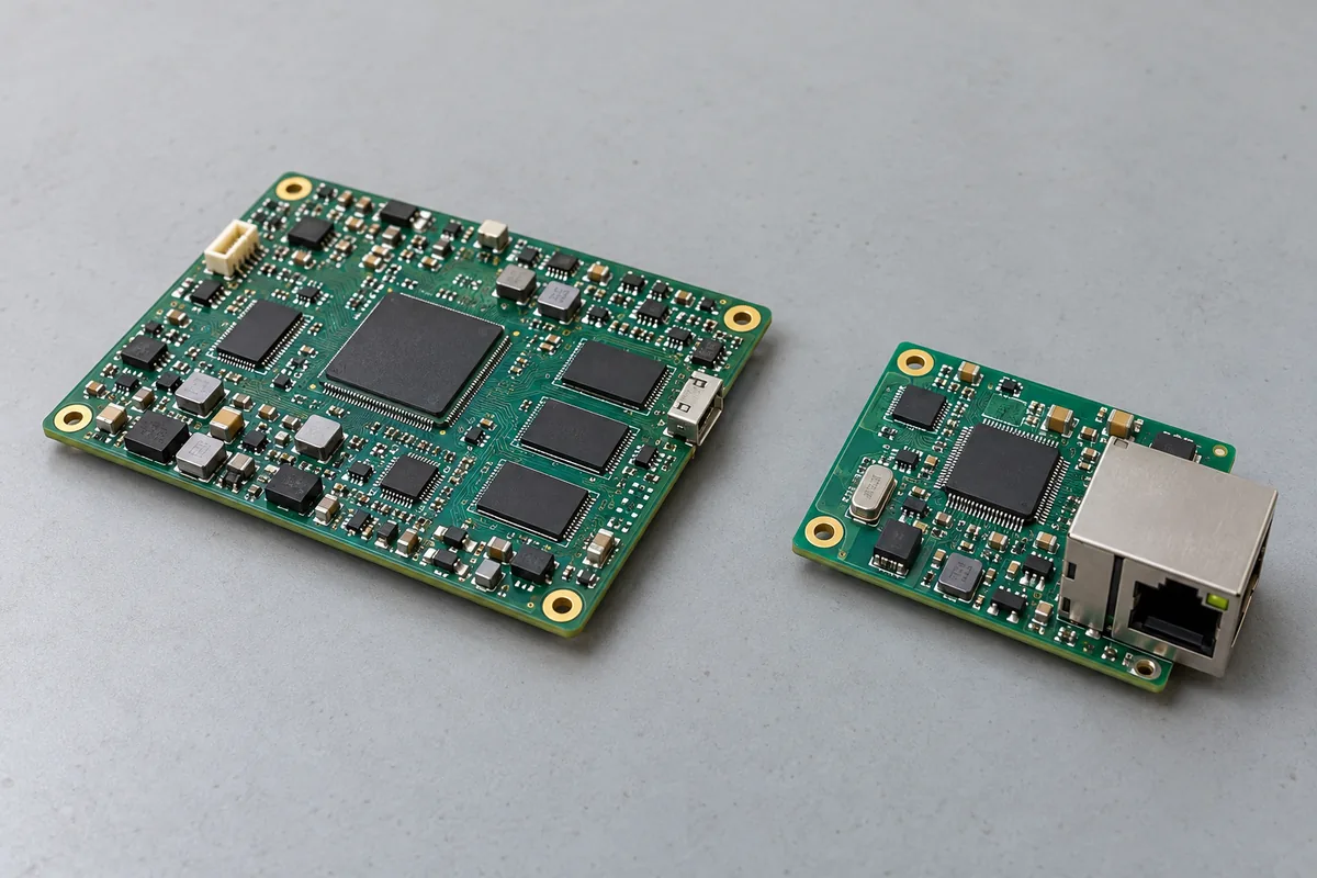
Management consumers can occupy separate physical assemblies. A management daughterboard, a network interface, and circuitry on the motherboard may all contribute to one auxiliary budget. Their physical separation helps explain why a controller-only figure can omit required demand, although an actual host schematic must establish which assemblies receive standby power.
Consider the following hypothetical load schedule. Every numerical value is an invented application input measured or estimated after local regulation. The figures are neither typical server consumption nor specifications for either manufacturer candidate discussed later.
| Hypothetical consumer group | Managed host-off state | Power-on interval | Scope of assumed demand |
|---|---|---|---|
| Management processor and memory | 6W | 8W | One combined board-level allocation |
| Required management network path | 2W | 2W | Networking circuitry excluded from the first row |
| Inventory and control circuitry | 1W | 1W | Other required auxiliary consumers |
| Total at regulated loads | 9W | 11W | Simultaneous downstream demand |
The second column describes sustained availability; the third captures an assumed overlap during power-on. These are separate required states. Combining the largest entry from every possible operating mode is appropriate only if those demands can actually coexist. Excluding a concurrent consumer because it runs briefly would create the opposite error.
For an actual design, replace each assumed entry with applicable component limits or representative board measurements. Record enabled features and installed options beside the values. A management expansion option that shares the same auxiliary source changes this schedule even when the server’s processors, drives, and main-output requirement remain unchanged.
Read the standby entries without enlarging their promise
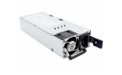
The LPS S1M-851CGP2 specification identifies an 850W CRPS product and lists a +12V standby output at 3A. Multiplying its nominal voltage by its listed current gives 36W. That arithmetic describes the nominal voltage-current product; it does not independently establish operating-state permission, simultaneous-output allocation, or power delivered after host-side conversion.
Senao’s ERA85-CPA2V-BF datasheet V1.0 instead lists +5Vsb with a maximum current of 3A. Its nominal voltage-current product is 15W. The two documents therefore provide different auxiliary starting points despite their shared 850W designation and equal numerical standby-current entries. Neither is presented here as an interchangeable module or an approved substitute for the other.
Keep the document boundaries intact. The Senao table contains several output rows, so its standby entry should not be treated as permission to add 15W to an independently assumed full main-output allowance. The LPS sheet likewise needs an applicable combined-output definition before its main and standby maxima can be assumed simultaneous.
Most consequentially, the supplied specifications do not explicitly establish the required standby capability with main output disabled. The Senao table also lists a minimum main-output current, whose applicability to that state needs clarification. An output named standby is a useful lead, but its name cannot resolve those operating conditions.
This leaves a precise manufacturer question: for the offered model and applicable revision, what auxiliary current is supported while main output is disabled, under the required input and cooling conditions, and what loading rules apply after main output starts? Until answered, the numerical comparison below remains conditional. It can identify a capacity concern without authorizing the operating state.
Move the load budget upstream through local conversion
The hypothetical 9W and 11W totals belong to the regulated loads. Comparing them directly with a PSU standby entry would omit whatever power the intervening regulators and distribution consume. Use one boundary consistently: the demand arriving at the PSU’s auxiliary output.
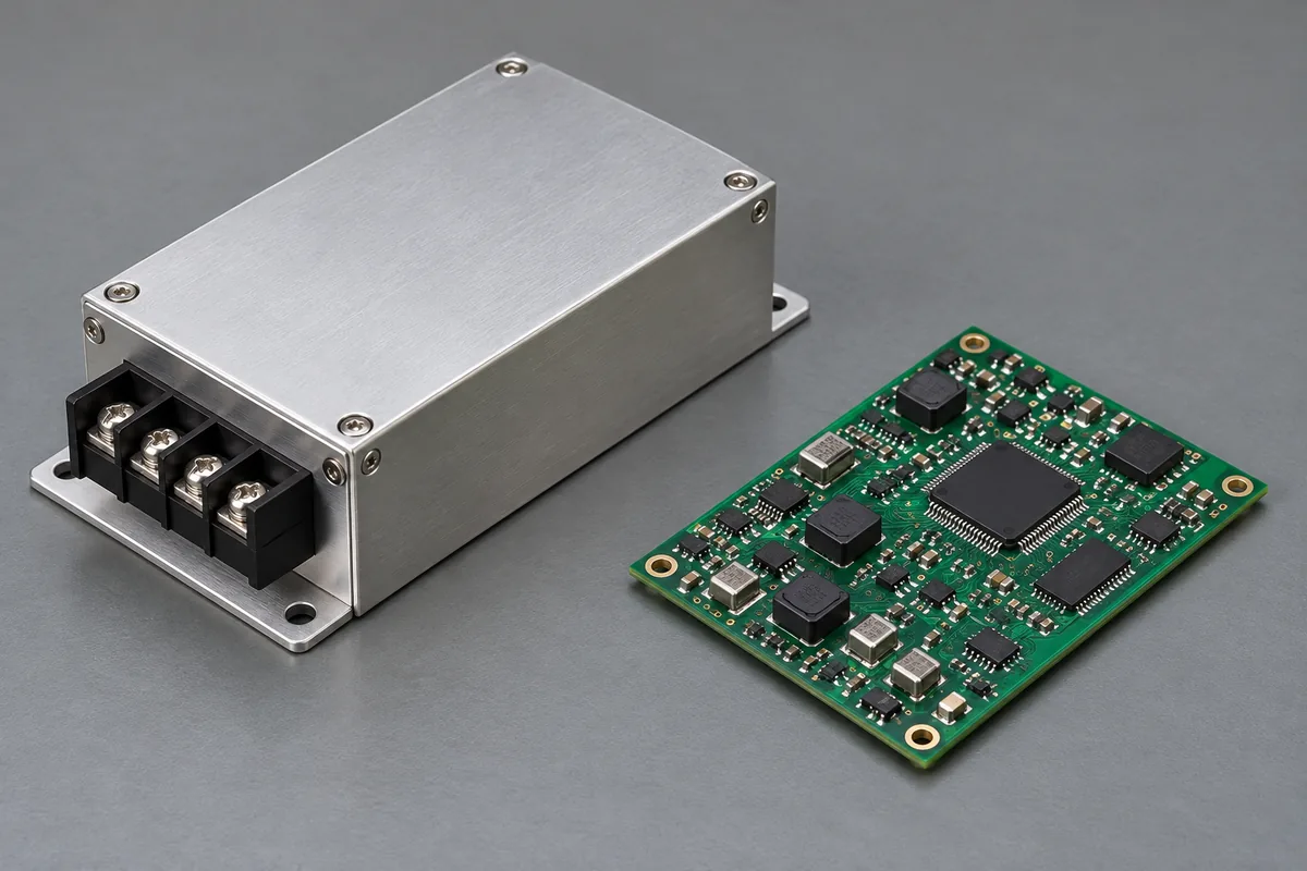
A separate DC-DC conversion stage can sit between the PSU’s standby output and the management electronics. That stage consumes input power while producing the lower voltages its loads require. Its presence changes the source budget even when the useful management functions remain identical. A compact converter is therefore part of the auxiliary-power arrangement, rather than free capacity supplied by the main-output rating.
For a deliberately simplified calculation, assume an aggregate conversion efficiency of 90% from the standby distribution node to the listed loads. Also assume another 0.5W consumed directly at that source boundary, outside those converted loads. These values are hypothetical and are applied equally only to demonstrate the accounting; actual 5V and 12V conversion arrangements can have different performance.
During the managed host-off state, required source power is 9W divided by 0.90, plus 0.5W, giving 10.5W. During the assumed power-on overlap, it becomes 11W divided by 0.90, plus 0.5W, or approximately 12.72W. These figures already include the stipulated conversion loss. Adding another efficiency allowance afterward would duplicate it.
At nominal 5V, those source demands correspond to 2.10A and approximately 2.54A. At nominal 12V, they correspond to approximately 0.88A and 1.06A. Comparing these calculated currents with the two listed 3A entries shows why equal ampere figures cannot be compared independently of voltage and the conversion arrangement.
Under these assumptions, both nominal comparisons fall below their respective published current entries. That is a limited arithmetic result. In particular, the 5V overlap leaves approximately 0.46A against the listed entry, before accounting for uncertainties or conditions absent from the simplified model. The calculation supplies no universal margin recommendation and does not close either candidate’s unresolved operating-state questions.
Actual budgeting should use the lowest efficiency applicable to the required load and operating conditions, along with any consumption excluded from that efficiency definition. For a constant-power demand, lower source voltage raises input current. Distribution drop can further reduce the voltage available to a local converter. Use the documented voltage window and converter behavior when calculating the actual maximum current.
The smaller nominal current associated with the 12V example does not establish a superior overall implementation. Converter selection, voltage compatibility, installed distribution, and supported operating states still determine whether that architecture can serve the host. Here, the calculation answers the narrower question of how much source demand the stipulated consumers create.
Keep management demand attached to the power-on sequence
A remote power-on request can increase auxiliary demand before main-powered circuitry becomes available. The hypothetical schedule captures that possibility by increasing management processor and memory demand from 6W to 8W. Whether a real host experiences that increase, and when it occurs, must come from its actual hardware and firmware behavior.
Describe the interval in functional terms. The management controller receives the request, performs its permitted checks, and initiates the host’s documented main-output sequence. Some auxiliary consumers may remain supplied from standby throughout. Others may transfer to another source if the host implements that behavior. Do not assume that main-output availability automatically unloads standby.
A transfer arrangement requires its own evidence. The receiving circuitry needs acceptable power during the transition, and the two sources need a supported connection method. A designer should not solve a standby shortfall by simply connecting main and standby outputs together. The permissible circuit and its control belong to the host design.
Average power also leaves short events unresolved. Charging local capacitance, enabling another regulator, or initializing an auxiliary device can create demand beyond a settled reading. A current entry alone does not establish response to that event. Where the requirement depends on such behavior, obtain the applicable load-step, startup, or capacitive-loading definition instead of inventing a permissible excursion.
The auxiliary sequence can expose a circular dependency. If circuitry needed to enable main power receives power only after main power starts, another supported startup provision must resolve that relationship. The management-load schedule should identify those initiating circuits explicitly. Assigning their watts to the eventual running state would conceal their earlier need.
For a redundant host, repeat this auxiliary account for the required source-loss state. Main-output current sharing does not establish standby sharing, and two installed 3A entries do not automatically create a usable 6A auxiliary source. Determine which documented standby path supplies the management domain after the specified module or input becomes unavailable.
This is separate from calculating the main bus’s surviving capacity. A server can have sufficient main-power capacity while its required management service depends on an auxiliary path that has not been established. Keep each function associated with the source arrangement that actually supports it.
Feature concurrency can change the budget without changing the PSU
Return to the hypothetical 5V calculation. Suppose a required management option adds 3W downstream during both states. Managed host-off demand becomes 12W at the regulated loads; the power-on interval becomes 14W. With the same assumed 90% conversion efficiency and 0.5W direct consumption, source demands become approximately 13.83W and 16.06W.
At nominal 5V, the latter requires approximately 3.21A, exceeding Senao’s listed 3A entry. The original host-off comparison still fits arithmetically, but the expanded power-on interval does not. This example shows how a reachable management interface before startup can coexist with a budget shortfall during the very action that interface initiates.
The appropriate response follows the service requirement. If the added option must remain active throughout startup, retain its demand and investigate a supported auxiliary arrangement with adequate capacity. If the option can legitimately wait until another documented source becomes available, scheduling it later changes the required simultaneous load. That is a functional change requiring host support, rather than an assumed electrical allowance.
The 12V example would have a lower calculated current for the same stipulated source watts, but that does not approve an LPS installation or establish its main-disabled behavior. Nor would moving to a higher main-output wattage establish more standby capacity. The replacement candidate’s auxiliary specification must answer the changed requirement directly.
Commercial scope remains a separate question. Powernexu’s discussion of comparing 850W modules and complete assemblies addresses what a quotation contains. For this management-power task, the useful result is the simultaneous consumer schedule, its translated standby demand, and the exact operating-state statement still needed from the manufacturer.
Neither supplied candidate can yet be approved for the defined host-off duty. Their standby entries make the capacity questions concrete; the missing permission for main-disabled operation and simultaneous output loading determines whether those entries can become an operating commitment.