The receiving equipment determines where redundant power paths can usefully meet. A single-input DC load needs a supported arrangement that delivers power through that one interface. Equipment with documented independently usable inputs may instead accept separate distribution paths, leaving source selection or combining inside the receiving assembly. Buying a redundant power distribution board before establishing that distinction can place a shared connection exactly where the equipment design intended separation.
This article examines that architectural choice: combine sources before the load, or preserve separate feeds to its documented inputs. It does not assign either topology to an unidentified commercial board. The important evidence starts at the receiving interface, including its return connections and permitted operating states, rather than at the number of upstream supplies.
A single receiving input puts the combining function upstream
A load with one documented supply-and-return interface presents one electrical destination. If either of two sources must sustain that load, some supported arrangement must make their energy available at that destination. That arrangement might use source ORing, controlled selection, or another documented implementation. The requirement identifies a function; it does not authorize joining arbitrary regulated outputs.
In a conceptual combined-bus arrangement, source A and source B each approach a supported source-isolation stage. Their outgoing paths converge before the load input. The load return completes a circuit back to whichever source supplies current. Isolation placement and return connectivity must come from the actual design, particularly where sources have grounding or galvanic-isolation requirements.
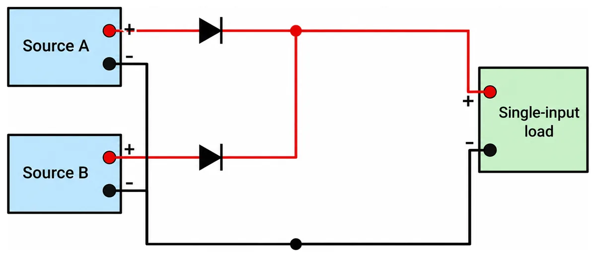
The resulting continuity promise has a defined scope. Losing one source can leave the load supplied through the other path if its capacity, isolation behavior, and transition response meet the receiving equipment’s requirements. The common output connection remains part of both alternatives. A failure there is a different event from loss of either source.
Separate output connectors on the distribution board do not necessarily change that boundary. Several connectors can be branches of one combined bus. Connecting two such branches to a receiving assembly does not create separate source domains if both branches already depend on the same junction. Count electrical relationships rather than sockets when describing the arrangement.
This can be an appropriate architecture for a single-input controller, storage subassembly, or other defined DC load. It preserves the receiving interface while moving source management into an upstream assembly. The trade-off is a shared delivery section between the source-combining point and the load. Its acceptability follows the required failure coverage.
Powernexu’s existing discussion of redundant distribution-board architecture explains ORing, sharing, and branch protection within that arrangement. Those mechanisms answer how a combined bus behaves. The earlier architectural question is whether a combined bus is the interface the receiving equipment actually needs.
Two documented inputs can move the meeting point into the equipment
Equipment with two power connectors presents a different possibility, but connector count leaves the essential questions open. The inputs might be alternatives, jointly required feeds, or connections serving different internal loads. Only applicable manufacturer documentation can establish whether either input independently supports the required service and whether simultaneous connection is permitted. Coverage for startup through either input should be established separately.
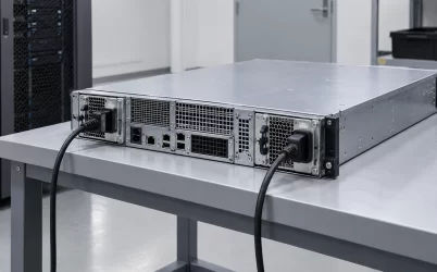
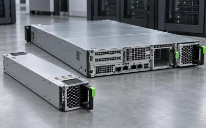
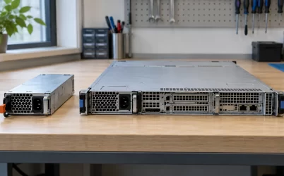
A generic enclosure with two separate input positions illustrates the physical distinction without proving electrical independence. Behind those positions, the equipment might contain two conversion paths, a source selector, a common bus, or separate consumers. A photograph cannot establish which arrangement exists. The input definition must connect the external interfaces to their supported functions.
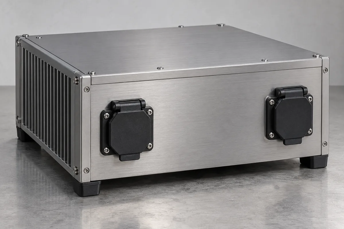
Where documentation supports independent operation from either input, retaining a separate distribution route to each can preserve separation farther downstream. Source A supplies the documented A interface through its own route; source B supplies the B interface through its own route. Any internal selection, combining, or functional coordination then belongs to the receiving equipment’s documented architecture.
Combining both sources upstream and splitting the resulting bus back into two leads changes that relationship. Both receiving inputs now depend on the same upstream output section. Such a connection might be permitted for a particular operating purpose, but it does not preserve two separate delivery domains through that section. Its acceptability needs an explicit installation basis.
Returns make this distinction more demanding than drawing two colored outgoing lines. Two routes can have separate supply conductors yet share a return terminal or conductor. Alternatively, an equipment design may intentionally bond references internally. Neither condition establishes a fault by itself, but both affect which parts remain common and which failures the proposed separation addresses.
Keep protective bonding distinct from the normal load-return function. A chassis connection may serve a protective or reference purpose without being the intended operating-current return. Conversely, two independently routed circuits need not be galvanically isolated. Use the manufacturer’s grounding and input requirements to describe those relationships; the phrase A/B power does not settle them.
Control can also cross the apparent boundary. A shared enable circuit may command both input stages, while a common controller may supervise them. Separate delivery paths can still be useful, but their benefit should be stated narrowly. They preserve the specified route separation; they do not establish independence from every internal equipment failure.
| Receiving arrangement | Distribution implication | Shared dependency to retain in the description |
|---|---|---|
| One documented power input | Provide a supported source-combining or selection arrangement before that input. | Common output section and receiving interface. |
| Two independently usable documented inputs | Separate routes may preserve source domains to the receiving boundaries. | Any shared returns, controls, enclosure, and internal equipment functions. |
| Two inputs required together | Supply both according to their assigned functions. | Loss of either required function may interrupt service. |
| Two connectors with undocumented roles | Topology remains unresolved. | Connector appearance establishes no continuity entitlement. |
The same continuity requirement can lead to different distribution purchases
Consider a hypothetical edge-control installation that must keep its specified control function operating after either designated DC source becomes unavailable. Assume its source voltages, capacities, and installation conditions will be supported by the eventual selected equipment. These are teaching assumptions, not specifications for a named product. Hold the required control service constant while changing the receiving interface.
First, suppose the controller has one documented DC input. Two separate distribution branches terminating near that input do not complete the architecture. The installation needs an approved way to supply that interface from either source. A distribution assembly incorporating the necessary source management could provide that function, or a separate supported redundancy device could precede ordinary distribution.
Next, suppose an alternative controller has two documented independently usable inputs, and its instructions permit simultaneous connection to the proposed sources. Separate distribution routes can now reach the controller directly. An upstream combining board is no longer automatically required to solve the single-input problem, because the receiving equipment provides a different supported power interface.
The two proposals deliver the same stipulated control function after the same source-loss event, but purchase different responsibilities. The first needs upstream source management plus a common delivery route. The second needs two suitable delivery routes and relies on the controller’s documented input behavior. Comparing board prices alone would conceal where the source-management work resides.
Now broaden the requirement to continued service while one distribution assembly is unavailable. The first proposal’s common combining assembly becomes central to that question. The second proposal might preserve one route if distribution assemblies are separate, but that outcome requires an actual arrangement that allows the affected assembly to be isolated without disturbing the other route.
A single PCB containing two sections does not automatically provide that maintenance capability. Shared mounting, common connectors, enclosure access, or a mandatory shutdown procedure can make both sections unavailable during service. Electrical separation and authorized replacement are different properties. The purchase comparison therefore needs to identify which service requirement each proposal actually addresses. If distribution maintenance is outside the requirement, avoid purchasing complexity solely to satisfy an unstated service objective.
The hypothetical comparison therefore has no universal winner. A single-input controller can justify upstream combining when preserving that controller is valuable. A documented dual-input alternative can justify separate distribution when downstream route separation serves the stated duty. The receiving hardware changes where the continuity function must be implemented, even before any wattage comparison becomes useful.
A board specification must connect to the chosen receiving boundary
Manufacturer terminology can help identify hardware without resolving this architectural choice. Systems Integrated’s SIPAC1 model 319-01-006 technical sheet names a redundant power distribution board and lists solid-state dual diodes per output and individual circuit breakers. Those stated features identify functions worth investigating. They do not, by themselves, provide a complete source-to-load connection definition for another installation.
The supplied sheet also contains input-current descriptions that are not sufficiently reconciled here to assign a surviving-path capacity. No numerical current allowance or dependent sizing calculation is adopted. More importantly for this article, a diode feature description does not establish how every source, channel, and return connects to the proposed load. An applicable functional drawing would address that relationship.
For a combined-bus proposal, the useful manufacturer evidence identifies where sources combine, which unavailable-source conditions are covered, and what reaches the receiving input. For separate-feed distribution, the evidence instead needs to preserve the intended separation through the offered assembly. A generic redundancy statement cannot answer both questions without describing the actual paths.
Assembly scope matters at this boundary. A server replacement PDB belongs to a documented host configuration, including its receiving interfaces and approved supply options. An industrial distribution board may require an integrator-defined enclosure and wiring arrangement. A facility distribution panel operates at another installation boundary. Their shared terminology does not make them alternative parts for one purchase.
For an existing server, retain the OEM’s supported power architecture rather than redesigning it around a generic board description. Two external server cords generally identify upstream PSU inputs; they do not establish two independently accessible DC load inputs. Changing the internal convergence point would be a platform engineering change, with consequences beyond replacing a distribution component.
For a new equipment design, the receiving interface can remain an architectural variable longer. A single-input load plus an external combining assembly and a supported dual-input load plus separate distribution can both deserve investigation. Include the receiving equipment, distribution hardware, required connections, and installation work in the comparison so that shifting a function does not make its cost disappear.
The connection boundary also affects later expansion. Adding another single-input consumer to separate source domains can introduce a new combining requirement for that consumer. Adding a documented dual-input consumer to a common bus does not recover separation already removed upstream. Treat each receiving assembly according to its input contract rather than extending one topology by visual symmetry.
The useful specification names where separation must remain and where convergence is permitted. For a single-input load, that can mean a supported combined supply delivered to one interface. For documented dual-input equipment, it can mean retaining separate routes to the two receiving boundaries. The board purchase follows that distinction: its job is to implement the required relationship between sources and the equipment that consumes their power.