A server power supply current-share circuit can lose useful current information at light load even while its output-isolation circuit operates as intended. This happens in a particular design approach: the same ORing MOSFET both blocks reverse current and supplies the voltage signal used to estimate branch current. If another controller deliberately holds that MOSFET’s forward drop nearly constant, the drop no longer tracks current in the simple way the sharing loop expects.
Texas Instruments documents this interaction in a UCC39002 load-share controller and TPS2412 ORing-controller example. It explains why changing the sensing element can change low-load balance without changing the nominal PSU rating. The example is a design reference, not evidence that an unidentified commercial server uses those components. Its useful lesson is about the information available to two interacting control loops, rather than a universal permissible current split.
One MOSFET can serve two different control questions
The ORing controller asks whether a source should remain connected to the common bus. Its external MOSFET provides a low-loss forward path and can be turned off when the voltage relationship indicates a reverse-current condition. The share controller asks how much each participating source contributes, then adjusts supported converter feedback to bring their contributions toward the intended distribution. Those questions remain separate even when both controllers observe the same power component.
A dedicated shunt resistor offers a straightforward current signal: its voltage drop is proportional to current through its resistance. That resistor also dissipates power. Using the ORing MOSFET’s on-resistance instead can avoid adding a separate sensing resistor to the high-current path. However, the familiar voltage-equals-current-times-resistance relationship becomes a useful current estimate only when the effective resistance is understood under the actual operating conditions.
For a fully enhanced MOSFET, drain-to-source voltage can provide information about current through its on-resistance. That does not make the MOSFET a precision resistor. Its resistance depends on operating conditions, and the isolation controller can deliberately change its gate drive. A sensing scheme that overlooks the latter effect can interpret controlled forward voltage as though it were an uncontrolled resistive drop.
The existing explanation of server PSU current sharing covers set-point mismatch, droop and the division of load between modules. Here the narrower question begins after active sharing has already been chosen: does the selected sensing path still report the quantity that its feedback loop needs?
The regulated forward drop creates a low-load blind spot
In its documented linear-control mode, TPS2412 adjusts the MOSFET gate to regulate the forward voltage between its A and C sense points to 10 mV. When the voltage expected from fully enhanced on-resistance and drain current exceeds that level, the controller drives the gate high and the MOSFET operates fully on. These are two different operating regions of the same component.
Below that transition, the controller can vary the channel’s effective resistance to maintain approximately the regulated drop. Two branches carrying different currents can therefore present similar forward-voltage signals. A sharing controller observing those drops receives little useful information about their difference. This is an interaction between the measurement method and gate control, not evidence that the branch currents have become equal.
TI’s Current Sharing in Redundant Systems application report describes the resulting light-load distribution as depending primarily on converter droop characteristics and path impedance. At higher current, once the MOSFET is fully enhanced, its voltage drop again changes with current through its on-resistance, allowing the sharing scheme to work more effectively. The report compares this approach with separate power-resistor sensing.
The 10 mV value belongs to this controller example. It is not a universal server-PSU threshold. Nor does it identify one fixed current at which every implementation changes behavior. The crossover depends on the selected MOSFET’s applicable on-resistance. Replacing that device, changing its gate-drive conditions or changing its temperature can alter the current associated with the boundary.
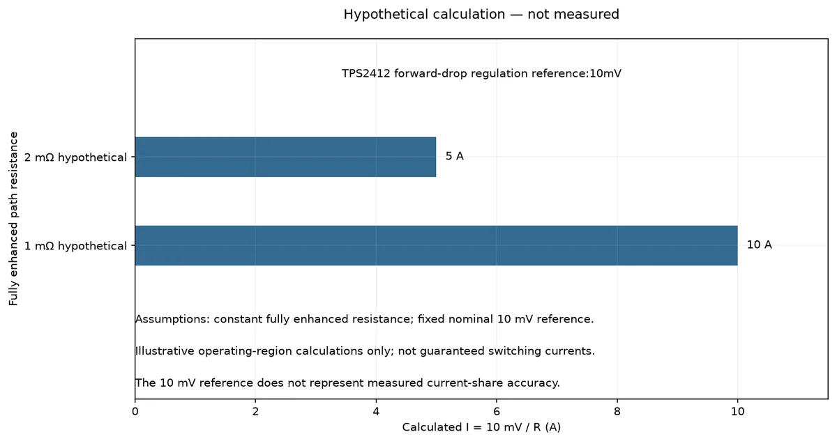
For illustration, suppose a hypothetical fully enhanced path has 2 milliohms of resistance. A 10 mV resistive drop corresponds to 5 A because current equals voltage divided by resistance. This calculation identifies an illustrative operating-region boundary; it does not specify a server’s minimum load, sharing tolerance or allowed operating current. Real analysis needs the actual controller behavior and applicable MOSFET resistance.
The calculation also exposes a counterintuitive trade-off. If the hypothetical on-resistance falls from 2 milliohms to 1 milliohm while the regulated forward drop remains 10 mV, the corresponding boundary rises from 5 A to 10 A. A lower-resistance device can reduce conduction loss when fully on, yet extend the current range in which linear gate regulation prevents its drop from acting as a simple current signal. This comparison holds the controller threshold fixed and ignores other device changes. It explains a sensing consequence; it does not establish which MOSFET is preferable for a complete design.
A separate shunt buys a more independent signal
Adding a current-sense resistor changes what the share controller observes. The shunt drop still follows branch current when the ORing controller adjusts the MOSFET gate. Sharing no longer relies on the isolation MOSFET remaining in its fully enhanced region. That independence is valuable when accurate low-load current division is part of the design objective.
There is an electrical cost. A resistor in the power path dissipates current squared times resistance, so a sensing choice that looks harmless at idle can matter at sustained load. Reducing its resistance limits dissipation but also reduces the signal available to the amplifier. Offset, noise, gain selection and physical sensing connections then become important to how faithfully the controller distinguishes the branches.
TI’s UCC39002 datasheet describes a differential current-sense amplifier with configurable gain and permits appropriate high-side or low-side sensing arrangements. Those capabilities belong to that controller and its allowed electrical conditions. They do not authorize connecting an arbitrary server share pin to an external shunt, or modifying a finished module’s feedback circuit.
| Sensing approach in the documented design | Useful signal | Consequence that needs attention |
|---|---|---|
| Dedicated current-sense resistor | Resistor voltage tracks branch current independently of MOSFET gate regulation | Additional conduction loss and a small signal requiring suitable amplification |
| ORing MOSFET voltage | Fully enhanced channel drop can indicate branch current | Linear forward-drop control reduces current information at light load |
The choice therefore concerns where accurate sharing is needed and what loss the design can accept. If a project needs tight low-load balance, eliminating the shunt may remove useful information precisely in that region. If high-load distribution is the main concern, the MOSFET-sensing approach may remain attractive. Neither conclusion establishes the performance of a complete PSU without its circuit and operating conditions.
The adjustment connection belongs to the combined circuit
The share controller needs a way to influence the converters after measuring their currents. In the UCC39002 architecture, follower modules are adjusted upward through a supported remote-sense or feedback arrangement. The controller with the leading current information establishes the share-bus reference. This is an active feedback system; the common current-share wire does not carry the server’s load current.
The converter must provide the required access and adjustment range. TI explicitly makes remote sensing or access to the converter’s feedback divider a condition of its implementation. A generic external board cannot create that access inside a sealed server cartridge merely because the cartridge supplies the correct voltage. The same limitation applies when a module’s published control interface is unavailable or platform-specific.
SLUA550 also changes the adjustment-resistor connection when moving to MOSFET-based sensing. The report connects the adjustment resistors to the common bus after the ORing MOSFETs and explains that the common reference simplifies the control interaction. The location matters because the isolation controller can alter the relationship between a converter’s local output and the joined bus.
That observation is specific to the illustrated circuit. It should not be turned into a rule to move every server’s sense leads downstream. A remote-sense connection is part of its designed regulation path, and changing it changes the feedback system. The useful integration question is whether the current sensor, adjustment point and ORing behavior were analyzed together, using the actual schematic.
Bandwidth adds another distinction. A sharing loop should not be assumed to correct branch currents instantaneously during every load edge. The UCC39002 design procedure relates its compensation to the power module’s measured response. Consequently, a short current difference during a transition and a persistent difference after settling need separate explanations. Neither one can be judged from a full-load accuracy statement alone.
Changing the gate-control method exchanges limitations
TI identifies TPS2413 as a different option when low-load sharing accuracy is desired in this example. It uses an on/off method with hysteresis rather than the TPS2412’s linear forward-drop regulation. That changes how the MOSFET voltage behaves between switching events and avoids the same continuously regulated forward-drop region.
The alternative introduces its own concern. TI explains that, unless a minimum load is maintained, the turnoff threshold must be negative to avoid an unstable light-load condition in this application. A negative threshold permits some reverse current before turnoff. The design decision therefore includes reverse-current behavior, rather than treating improved sharing as an isolated benefit.
The TPS2412/TPS2413 datasheet also distinguishes their responses to steps from light load. Linear gate regulation and fully on operation do not begin with the same effective channel resistance. Gate charging and the converter’s response can influence bus voltage during the transition. The result depends on the complete power path, so selecting a controller from a static sharing comparison alone misses part of the problem.
Replacing one controller with the other is consequently a circuit redesign, even where their purpose appears similar. Threshold programming, load behavior, gate drive, capacitance and permitted reverse current remain coupled. This article does not recommend changing an installed server’s ORing circuit; it explains why a component choice can improve one observation while changing another operating boundary.
What the reference example lets an engineer conclude
TI’s report demonstrates its approach using evaluation hardware on a regulated 5 V bus. Its measured results belong to that setup. They are not measured behavior of a modern 12 V server cartridge, a 48 V shelf or a Powernexu product. The mechanism can inform another design, but numerical sharing accuracy and transient performance must come from that design’s evidence.
For a finished server, the first missing fact may be simply which sensing method it uses. Management telemetry usually cannot establish that from a current ratio alone. A low-load imbalance might reflect this control interaction, an intentional standby policy or another cause. Treat the MOSFET-sensing explanation as a circuit-dependent hypothesis until manufacturer documentation identifies the implementation.
For a platform designer, the reference supplies a sharper question than whether two converters are parallel-capable. Identify the element producing the current signal and ask whether another loop controls its voltage independently of current. If the answer is yes, establish which operating region restores a useful current-dependent signal and whether the intended sharing requirement extends below it.
The central distinction is between current flowing and current being observable to the sharing controller. An isolation MOSFET can pass power correctly while providing poor information for balancing two sources. Separating those functions explains why an acceptable low-loss power path can still need a different sensing arrangement, and why equal forward-voltage readings need not mean equal branch currents.