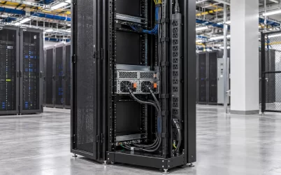
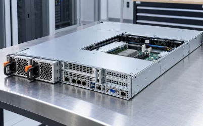
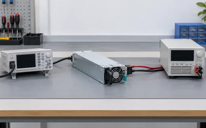
Server power supply current sharing is the controlled division of one DC load among two or more active PSU modules. It is not guaranteed merely because the modules have equal wattage or their outputs meet at a power distribution board. Small differences in output-voltage set point and path impedance can make one module carry more current; if that module reaches a protection or thermal limit first, the server may lose stability even though the sum of the printed ratings looks adequate. In a redundant system, current sharing must support both ordinary operation and the transition to the remaining modules after one source is removed. The host’s approved PSU-PDB combination defines the intended behavior.
Why two regulated outputs do not naturally split a load
Imagine two ideal voltage sources feeding one bus. If both held exactly the same voltage at their terminals and had zero impedance, their current division would not be determined by those facts alone. Real converters are not identical ideal sources. One may regulate slightly higher than the other, and its connector, busbar, wiring, and sensing path may have a different effective impedance. The higher-voltage path can supply most of the load while the other contributes little until bus voltage changes. That is why a photograph of two powered modules is not evidence of balanced sharing.
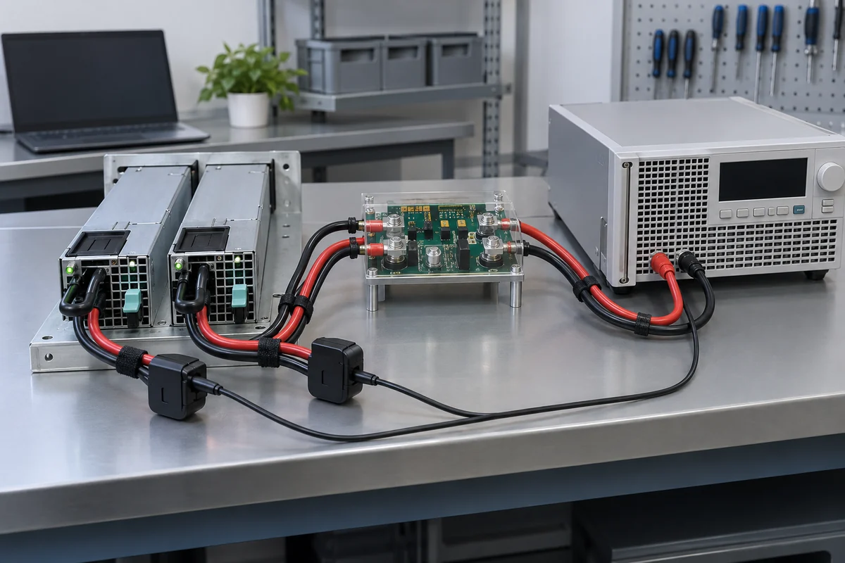
The electrical problem is documented in CUI’s technical paper on current sharing: directly paralleling outputs does not ensure an acceptable distribution, and set-point error can cause one supply to reach its current limit before the expected combined current is delivered. The paper explains general methods and their trade-offs; it is not a specification for every server PSU. In a real server, the module manufacturer and platform designer define which sharing method and interface are supported.
Suppose a hypothetical 12 V bus serves a 100 A load through two nominally equal modules. Perfect equal sharing would be 50 A each. A 60/40 split may still be within both modules’ supported limits, or it may be unacceptable if the first module is already thermally constrained. The number alone does not establish a fault. To interpret it, know the permitted sharing tolerance, load range, inlet conditions, and whether the host expects active-active operation or a different supported policy. Current sharing is not always synonymous with exactly half the current at every instant.
Sharing control can be active or deliberately drooped
Some parallel supplies use a dedicated current-share signal or control loop. Each converter adjusts its output behavior in response to information about the group, seeking a controlled distribution of load. The exact bus, signal scaling, command behavior, and response to a missing member are design-specific. A compatible mechanical CRPS outline does not prove that two revisions share the same control implementation. The PDB must route or support the intended signaling, and the server must approve the module combination.
Another approach deliberately allows output voltage to fall slightly as delivered current rises. A module carrying more current then experiences more droop, creating an incentive for the lower-current module to take a larger share. This can work without the same kind of coordination signal, but the droop reduces voltage regulation at the common bus. The amount must be compatible with downstream converters and the load’s voltage requirements. Adding series resistance to manufacture droop also creates heat proportional to current squared times resistance. It is not a free balancing adjustment.
Remote voltage sense can interact with droop. A sense loop designed to restore voltage at the load may counteract the intentional voltage fall that made passive sharing possible. The CUI paper calls out this conflict in its general parallel-supply analysis. A server integrator should follow the module and PDB design for sense wiring rather than move sense points to “improve regulation” by intuition. A change that looks beneficial on a static voltmeter can destabilize the intended current distribution.
Many server designs also isolate outputs so a failed or unpowered module cannot draw energy backward from the live bus. Isolation and sharing solve different problems: one governs current distribution while healthy, and the other contains a fault or inactive path. The isolation device or method introduces its own loss, heat, control behavior, and transition requirements. Seeing an ORing function in a PDB does not prove the modules will share evenly; seeing a share pin does not prove a shorted output is isolated.
Unequal current has a local thermal consequence
A moderate current imbalance may concentrate loss in one PSU and its mating contacts. If the common bus carries 100 A and one input supplies 65 A while the other supplies 35 A, the heavier path can have higher conduction loss, hotter connector contacts, and more fan demand. The exact temperature difference depends on path resistance, cooling, and converter efficiency, so it cannot be inferred from current alone. Nevertheless, the I²R relationship means a high-current path deserves attention even when aggregate bus power is within the system rating.
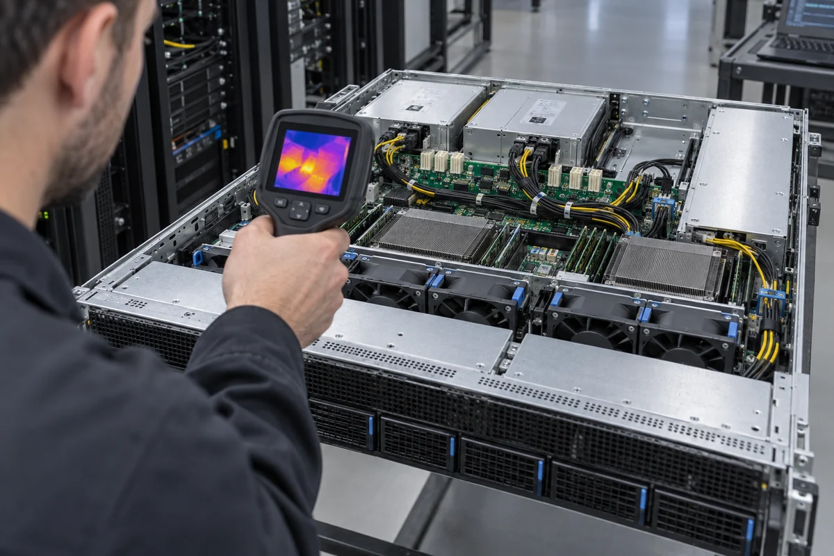
The location of a current reading matters. A BMC may report per-PSU output power, not direct current, and its update interval may smooth fast changes. A rack PDU reports AC input per outlet, which includes converter losses and may not split in the same proportion as DC output. A board-level current sensor may include one branch but not another. Compare synchronized measurements with known boundaries before concluding that the share controller is defective. Different efficiency at each module’s operating point can produce unequal AC readings even when DC currents are similar.
Airflow can make an imbalance more consequential. Two modules side by side may not see identical inlet temperature if one is near recirculated exhaust or a blocked intake. A module carrying somewhat more current while also receiving warmer air may approach a thermal limit earlier than its mate. A healthy share mechanism does not erase these environmental differences. The finished chassis, fan policy, and connector temperature determine whether the observed distribution is acceptable under the actual load.
Current-sharing tolerance is usually evaluated over a specified range rather than at one operating point. Near light load, control resolution, minimum operating power, and standby policies can produce a very uneven split without threatening capacity. At high sustained load, the allowable imbalance may be much more important. Therefore a single idle reading cannot certify the subsystem, and an apparent imbalance should be interpreted against the platform’s published operating mode before someone tries to retune anything.
The failure transition is a different electrical event
During normal operation, two modules may both feed the bus. If one loses AC input, shuts down, or is removed, the survivor must take over the load permitted by the redundancy policy. The transition is dynamic: bus capacitance, output control loops, isolation devices, module response time, and downstream converters all affect voltage behavior. An acceptable 50/50 or 60/40 steady-state share is not proof that the server will remain inside its voltage limits during removal. Conversely, a host designed for a standby mode may not exhibit steady-state sharing at all while still supporting a specified failover.
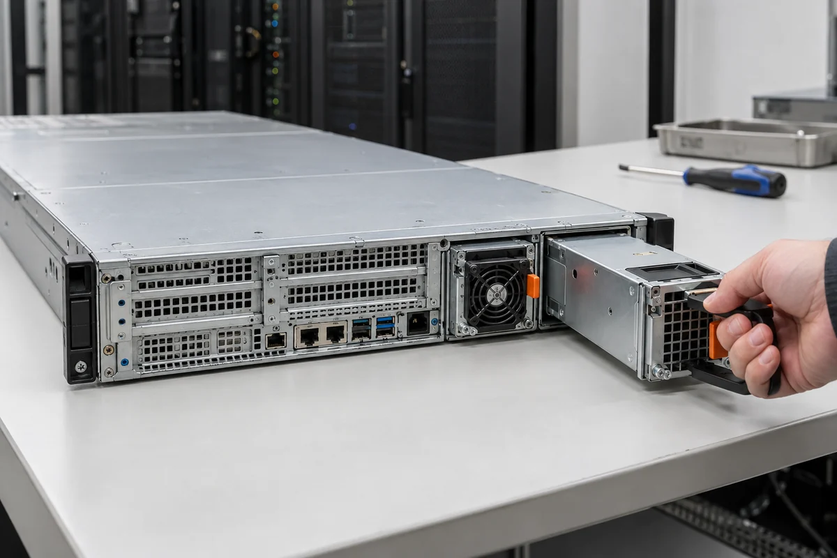
Protected capacity remains bounded by the survivors. In a two-module 1+1 server, either remaining module and its PDB path must carry the allowed load after the other disappears. If the server is permitted to demand 1,300 W but one module can support only 1,200 W under the installed conditions, balanced operation with both present does not create a 1,300 W redundant system. The host may apply a power cap or throttle on failure if its documented policy allows that. Be explicit about whether continuity means staying powered or maintaining full performance.
Recovery is also part of the event. When a repaired or new module enters a live system, it should not abruptly seize current or disturb the bus through inrush, reverse current, or control-loop conflict. Connector sequencing and hot-swap control are relevant only for assemblies designed for live insertion. Never use a generic bench parallel experiment as permission to insert an unapproved PSU into a running server. The electrical interface, module identity, and service procedure are all platform-specific.
What a useful current-share observation includes
For an already integrated server, begin with the mode reported by the host: active sharing, hot standby, or another documented policy. Note the installed module part numbers and revisions, input status, server load, and any power cap. Then observe per-module DC output or current through the system’s supported telemetry, if it provides those fields. If only AC input per cord is available, use it as an input-energy observation rather than treating it as direct evidence of equal DC current. Identify whether the readings are averaged and whether the load was stable during the sample.
For a new platform design, the relevant evidence extends beyond a screenshot of two PSU values. Review the supported module-PDB pairing, share interface, sense wiring, isolation method, connector and copper limits, load range, and thermal arrangement. Evaluate steady operation at relevant low, normal, and high load, then the permitted loss of a module and its controlled restoration. This is not a generic acceptance checklist to paste into a purchase order: the observed waveforms, measurements, and limits must come from the actual design and its stated failure objective.
A suspicious split has several possible causes. Different module revisions or firmware can alter behavior; poor contact or unequal bus impedance can bias the apparent output; a blocked fan or warm inlet can change a module’s limit; and a standby mode can look like failed sharing when it is operating as designed. Swapping cartridges or changing controller settings without identifying the supported mode can obscure the fault or defeat redundancy. Follow the host’s diagnostics and service instructions, and distinguish a control problem from a wiring, thermal, or measurement problem.
The same principle applies when interpreting a claim of “current share” in a datasheet. Ask what is shared, across which approved module population, over what load and input range, and with what allowed error. The word alone does not establish that any two equal-wattage PSUs can be paralleled, nor that a downstream board can carry the resulting current. A complete statement connects the converter behavior to the distribution path and the host’s operating policy.
Where equal sharing is not the goal
Some servers intentionally keep one module less active at light load or use a platform-specific energy policy. In that mode, near-equal current is not necessarily the desired steady state. The engineering question is whether the server’s chosen policy preserves its promised failure response, keeps each active component within rating, and yields the expected efficiency behavior. Disabling a supported power-saving mode merely to make two telemetry bars match could increase energy use without improving availability.
Current sharing is therefore best understood as controlled load allocation for a defined architecture, not as a visual symmetry target. When active-active operation is specified, the modules and PDB should divide current within the allowed range and survive the expected loss and reinsertion events. When a standby or other mode is specified, its normal imbalance must be judged against that mode’s documented behavior. The useful result is a stable bus and a surviving path that can carry the real server load—not two identical numbers on a management screen.