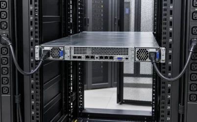
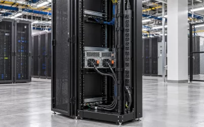
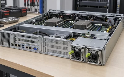
A tower server can use redundant power supplies, but adding a second PSU is not necessarily a matter of sliding another cartridge into an empty opening. Some tower models ship with a fixed single supply and require a manufacturer-approved redundancy enablement assembly; others have an integrated hot-plug cage from the start. The enclosure, power distribution hardware, output harness, and firmware must support the change. Before buying a spare or proposing an upgrade, identify the exact tower model and its supported power options. The practical question is whether that particular tower can carry its approved workload after one module or feed is lost—not whether two power cords can be made to fit behind it.
A tower with one PSU bay is not automatically upgradeable
Tower systems often resemble large desktop PCs from the outside. That visual similarity can mislead an integrator into treating a redundant supply as an ATX-like replacement. In a purpose-built server, the PSU may connect through a cage and power distribution board, supply management signals, and depend on a chassis-specific bracket or backplane. A single-supply version may have different internal wiring or no second module position at all. The absence of a visible second cartridge is not proof an upgrade is impossible, but an unused sheet-metal opening is not proof it is supported.
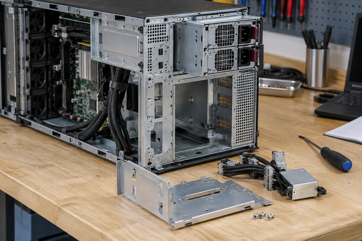
One concrete example is HPE’s documented Flexible Slot redundant power-supply enablement procedure for the ProLiant ML30 Gen10. The procedure calls for an enablement option and a hot-plug supply, and begins with powering down and removing cords and access panels. This does not mean every ML-series server uses the same kit or that every tower needs a shutdown for a later cartridge replacement. It demonstrates the distinction between installing a complete supported redundant subsystem and replacing an already installed hot-plug module.
For a prospective retrofit, obtain the server’s service guide and supported options list for its specific generation and chassis revision. Determine whether the change requires an enablement kit, second supply, cage, distribution board, harness, mounting hardware, or firmware level. A quote for “one redundant PSU” can omit much of that assembly. Also check whether installing the option consumes a bay or changes drive, fan, or expansion-card choices. The physical tower has more height than a 1U server, but that space may already belong to storage and cooling hardware.
The redundant assembly must match the tower’s permitted load
In a 1+1 tower configuration, one remaining module must support the workload allowed after the other fails. Two modules rated at 800 W each do not necessarily create 1,600 W of protected capacity. If the host’s approved processor, storage, and accelerator population can demand more than one module’s supported output under the site’s input and temperature conditions, the server may throttle, shed load, or lose the promised continuity. Those outcomes are platform-specific. The supported system configuration, not an arithmetic sum on a reseller listing, defines the usable boundary.
A tower may grow over time. New drives, higher-power processors, PCIe cards, additional memory, and fan changes can move its peak and sustained demand. A redundant option that was sufficient for an entry configuration may not protect every later configuration. The service manual may specify which PSU combinations are required for particular hardware. Review the actual installed components and intended expansion before treating a redundant kit as a permanent capacity guarantee.
The supply’s input rating matters as much as its output label. Some server modules deliver different maximum power on lower- and higher-voltage AC sources. An upgrade quoted using a high-line rating may provide less usable protected capacity at a site with a lower-voltage outlet. Check the exact module’s rating table and the tower’s support matrix; do not generalize a voltage derating rule across products. The PDB, connectors, and branch harnesses also need to support the failure-state current. A more powerful cartridge cannot expand a board or cable’s documented limit.
Consider a hypothetical tower whose validated maximum continuous DC demand is 650 W. A supported pair of 900 W supplies could in principle provide one-module survival if each supply is capable of at least that output under the installed conditions and the host supports the mode. If the tower later gains a card that lifts permitted demand to 1,000 W, the same pair might keep the machine running normally with both supplies but no longer protect the full configuration after one loss. The illustration says nothing about any real server model; it shows why expansion changes a redundancy claim.
Tower placement changes the cord and service problem
A rack server usually presents its PSU modules and cords into a planned rack cable space. A tower may sit beneath a desk, beside a production instrument, in a closet, or on a mobile service cart. The two AC cords can be easy to connect but difficult to trace after installation. If they enter adjacent sockets of one power strip, the server has module redundancy but not independent feed protection. If separate feeds are required, trace each cord to its intended outlet, circuit, UPS, and maintenance domain instead of relying on cord color or a handwritten label alone.
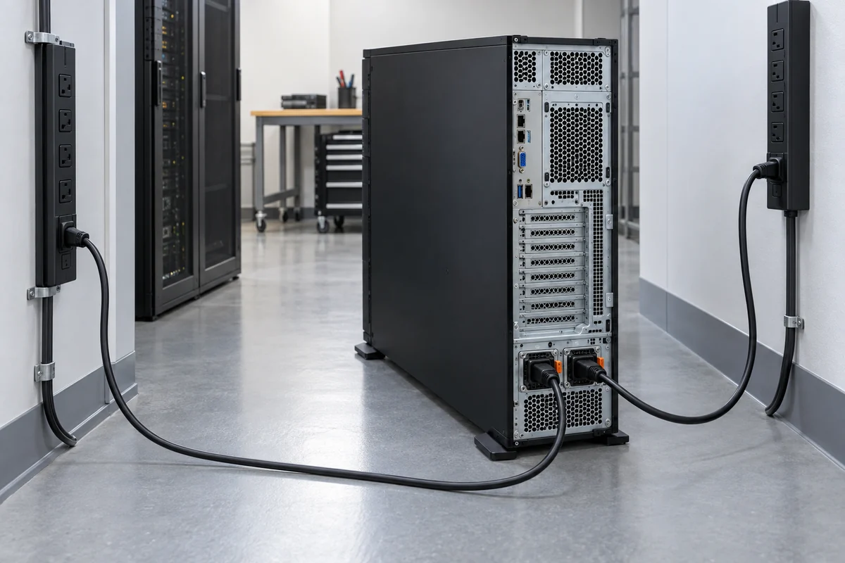
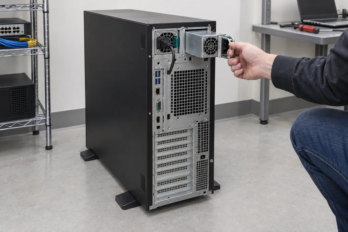
Keep the rear of the tower serviceable. A redundant cartridge may be removable only from the back, and a wall, cable bundle, security bracket, or neighboring device can block its extraction path. A power cord that crosses the other module’s handle can force an operator to disturb the healthy path while replacing the failed unit. Leave the clearance specified for the server, plan cord retention and bend radius, and check that the failed module can be identified from the accessible side. A tower placed in a tight furniture cavity can lose the practical advantage of hot-plug hardware.
Do not overlook furniture and housekeeping practices. A tower may be moved during cleaning, relocated to make room for another device, or placed on a shelf without the original installer present. Those changes can pinch a cord, obscure the PSU indicators, or reduce the exhaust gap while leaving the server apparently healthy. If the system’s availability depends on distinct power paths, document which cord belongs to which source in a way a local technician can verify without opening the machine. The installation should remain intelligible after normal room changes, not only on the day it is commissioned.
Room airflow also differs from an orderly rack aisle. A tower might take air through the front or side and exhaust it at the rear, but the route must be read from that model’s documentation. Surrounding furniture, dust filters, carpet, and nearby walls can raise inlet temperature or recirculate exhaust. Installing a second PSU can alter rear airflow and fan behavior. The condition that matters for the PSU rating is the air reaching the module in its actual enclosure, not the office thermostat. A successful bench installation does not prove that a floor-level tower will remain inside thermal limits months later.
Acoustics may matter in a tower deployment because it can sit in an occupied room. Redundant server PSUs often use compact fans and may change speed as load shifts to one surviving module. Do not promise a quiet result from an efficiency badge or a photograph. Use model-specific acoustic data where available and consider where people will work during both normal and degraded operation. Avoid blocking vents to solve a noise complaint; that can create a more serious thermal problem.
Replacement differs from a first-time upgrade
If the tower already has a healthy redundant cage and one PSU has failed, the service task may be a model-approved module replacement. Confirm the failed bay from indicators and management events, identify the exact supported spare part, and follow the manufacturer’s live-service procedure if the platform supports hot swap. Do not remove the healthy module to “test” a guess, and do not assume a visually similar cartridge has compatible keying, output, management, or firmware behavior. The server’s spare list is more authoritative than a marketplace photo.
A first-time upgrade changes the power subsystem. It may require powering down, opening the enclosure, replacing a distribution assembly, routing new harnesses, and checking the result through firmware. The HPE example shows why the word “hot-plug” on a module does not mean the initial enablement work occurs while the server is running. The distinction should appear in the work order: spare cartridge replacement is not the same operation as enabling redundancy in a single-supply tower.
Factory options and aftermarket kits should be distinguished as well. A manufacturer’s supported option can have specific mechanical, electrical, cooling, and firmware instructions for the host. A generic redundant ATX-sized assembly might physically occupy a similar volume but lacks automatic approval for the tower’s wiring, protective behavior, or management reporting. An integrator considering a nonstandard modification would own that compatibility and safety work; it should not be described as a simple field upgrade. For a business-critical tower, the availability of a controlled spare and support path can be more valuable than apparent savings on an unverified converter.
When a used tower is purchased, determine which hardware is actually present. A system advertisement may list redundancy as an option available for that model rather than as installed inventory. Photographs of the rear show bay count but not necessarily the PDB or internal harness. Request the installed part numbers, module population, and management screen that reports the current power state. If the seller has removed one module for resale, establish whether the remaining assembly is still complete and whether compatible spares can be sourced for the tower’s remaining service life.
Mixed module revisions may be restricted by the host, even when the chassis accepts both mechanically. Firmware can report an unsupported combination, power imbalance, or missing capacity. After replacement, verify that the tower recognizes both units and returns to its intended redundancy state. A green indicator on the new PSU is helpful but not sufficient if the management controller still sees an incompatible pair or no input on one side.
A supported tower can still have a common power failure point
Dual PSUs protect against only the failures included in the design and feed topology. They do not automatically protect the motherboard, distribution board, both cords through one power strip, or a single upstream UPS. If the tower supports redundant modules but uses one room circuit, that limitation may be acceptable for a small office or edge appliance—provided it is understood. For higher availability, the upstream architecture and application recovery plan must match the importance of the workload. The tower’s PSU pair is one layer, not a substitute for every other one.
Observe what happens after a controlled, manufacturer-approved loss of one path during a planned service window. The server should remain within its documented operating mode, report the fault, and restore its healthy redundancy state after the path returns. The exact procedure and whether a live test is appropriate depend on the host and site. This is not a call to unplug production equipment casually: the relevant insight is that the tower must both survive the defined event and make the degraded state visible to operators. A silently degraded dual-PSU system can wait for a second fault unnoticed.
The most useful ordering description names the tower model and revision, its approved redundant-power option or spare cartridge, the intended module population, site input voltage, protected server configuration, and whether the work is a retrofit or a replacement. That specificity prevents a generic “redundant tower PSU” from becoming an incomplete kit. In a tower server, redundancy is realized by the supported assembly and the way it is installed in a room—not by adding a second power-supply label to a parts list.